6–12 745 TRANSFORMER PROTECTION SYSTEM – INSTRUCTION MANUAL
A2 METERING CHAPTER 6: ACTUAL VALUES
The harmonic derating factor for each of the windings shows the effect of non-sinusoidal
load currents on power transformer’s rated full load current. The calculations are based on
ANSI/IEEE standard C57.110-1986. The actual values messages display the harmonic
derating factor for windings 1 through 3.
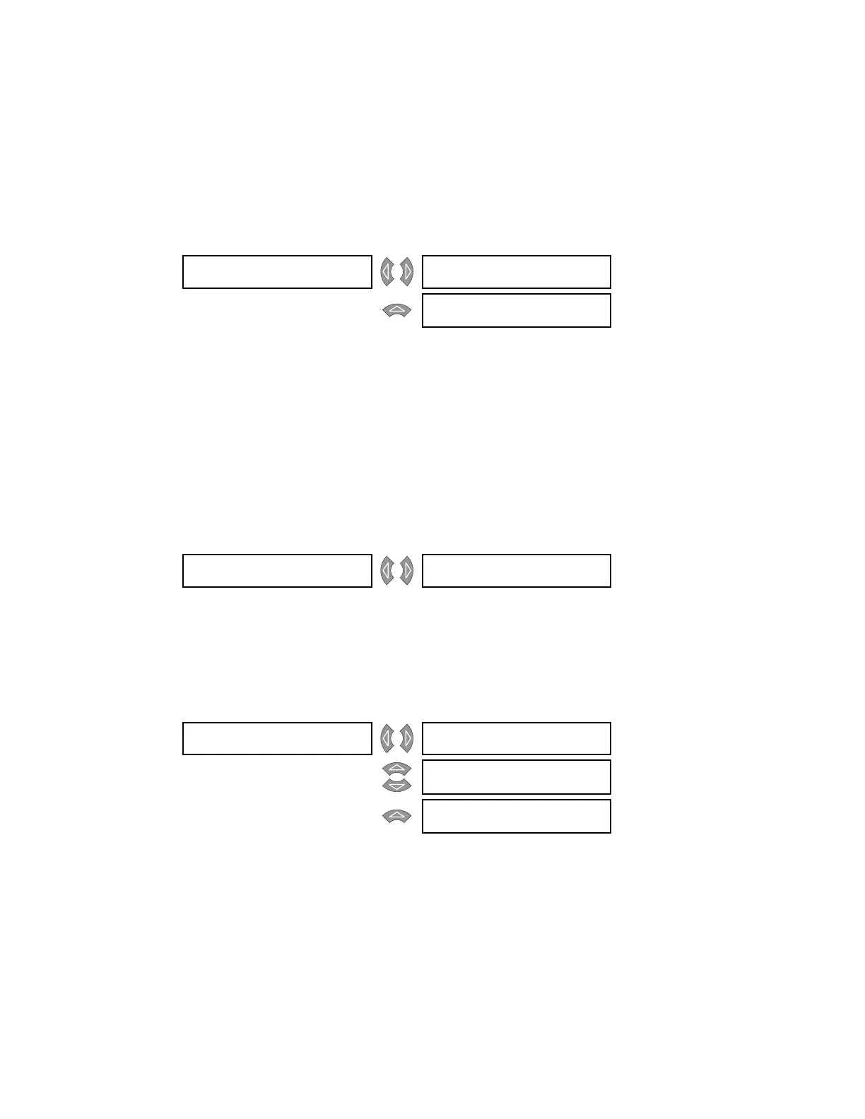
6.3.3 Frequency
PATH: ACTUAL VALUES A2 METERING FREQUENCY
The SYSTEM FREQUENCY is calculated from the voltage input provided that voltage
sensing is enabled and the injected voltage is above 50% of VT. If these criteria are not
satisfied, then it is determined from winding 1 phase A current provided that it is above
0.05 × CT. If frequency still cannot be calculated, “0.00 Hz” is displayed, though the
sampling rate is then set for the
S2 SYSTEM SETUP TRANSFORMER NOMINAL
FREQUENCY setpoint. The FREQUENCY DECAY RATE can only be calculated if system
frequency can be calculated.
6.3.4 Tap Changer
PATH: ACTUAL VALUES A2 METERING TAP CHANGER
This message displays the actual tap position. If tap position sensing is disabled, “n/a” will
be displayed.
6.3.5 Voltage
PATH: ACTUAL VALUES A2 METERING VOLTAGE
For phase-to-neutral input voltages, the SYSTEM LINE-TO-LINE VOLTAGE displays its line-
to-line equivalent.
FREQUENCY [] SYSTEM FREQUENCY:
0.00 Hz
MESSAGE
FREQUENCY DECAY
RATE: 0.00 Hz/s
TAP CHANGER [] TAP CHANGER
POSITION: n/a
VOLTAGE [] SYSTEM LINE-TO-LINE
VOLTAGE: 0.00 kV
MESSAGE
VOLTS-PER-HERTZ:
0.00 V/Hz
MESSAGE
LINE-NTRL VOLTAGE:
0.00 kV at 0° Lag