6–20 745 TRANSFORMER PROTECTION SYSTEM – INSTRUCTION MANUAL
A3 EVENT RECORDER CHAPTER 6: ACTUAL VALUES
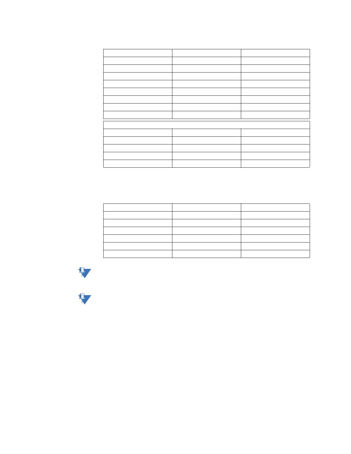
The following events are always logged. That is, they are logged regardless of any event
recorder settings (they cannot be disabled).
Note
The recorded event displayed for logic inputs, virtual inputs, and relay outputs will show
the programmed name of the input/output.
Note
If Power to the 745 is switched off before the relay is completely booted up and in service,
a false event could be recorded in the event recorder.
Virtual Input 9 Virtual Input 10 Virtual Input 11
Virtual Input 12 Virtual Input 13 Virtual Input 14
Virtual Input 15 Virtual Input 16 Output Relay 1
Output Relay 2 Output Relay 3 Output Relay 4
Output Relay 5 Output Relay 6 Output Relay 7
Output Relay 8 Self-Test Relay Virtual Output 1
Virtual Output 2 Virtual Output 3 Virtual Output 4
Virtual Output 5 Control Power Test Mode
Test Mode 2 Test Mode 3
ERROR! events
Logic Input Power Analog Output Power Unit Not Calibrated
EEPROM Memory Real-Time Clock Emulation Software
Int. Temperature FlexLogic Equation DSP Processor
Bad Xfmr Settings IRIG-B Signal Setpt Access Denied
Ambnt temperature Diagnostic Message 1
Table 6–2: Continually logged events
Setpoint Group 1 Setpoint Group 2 Setpoint Group 3
Setpoint Group 4 Simulation Disabled Simulation Prefault
Simulation Fault Simulation Playback Logic Input Reset
Front Panel Reset Comm Port Reset Manual Trace Trigger
Auto Trace Trigger Aging Factor Limit Ambient Temperature
Tap Changer Failure DSP Processor Test Mode 2
Test Mode 3 Diagnostic Message 1
Table 6–1: Types and causes of events (Continued)