7–4 745 TRANSFORMER PROTECTION SYSTEM – INSTRUCTION MANUAL
GENERAL CHAPTER 7: COMMISSIONING
• single-pole single-throw contactor
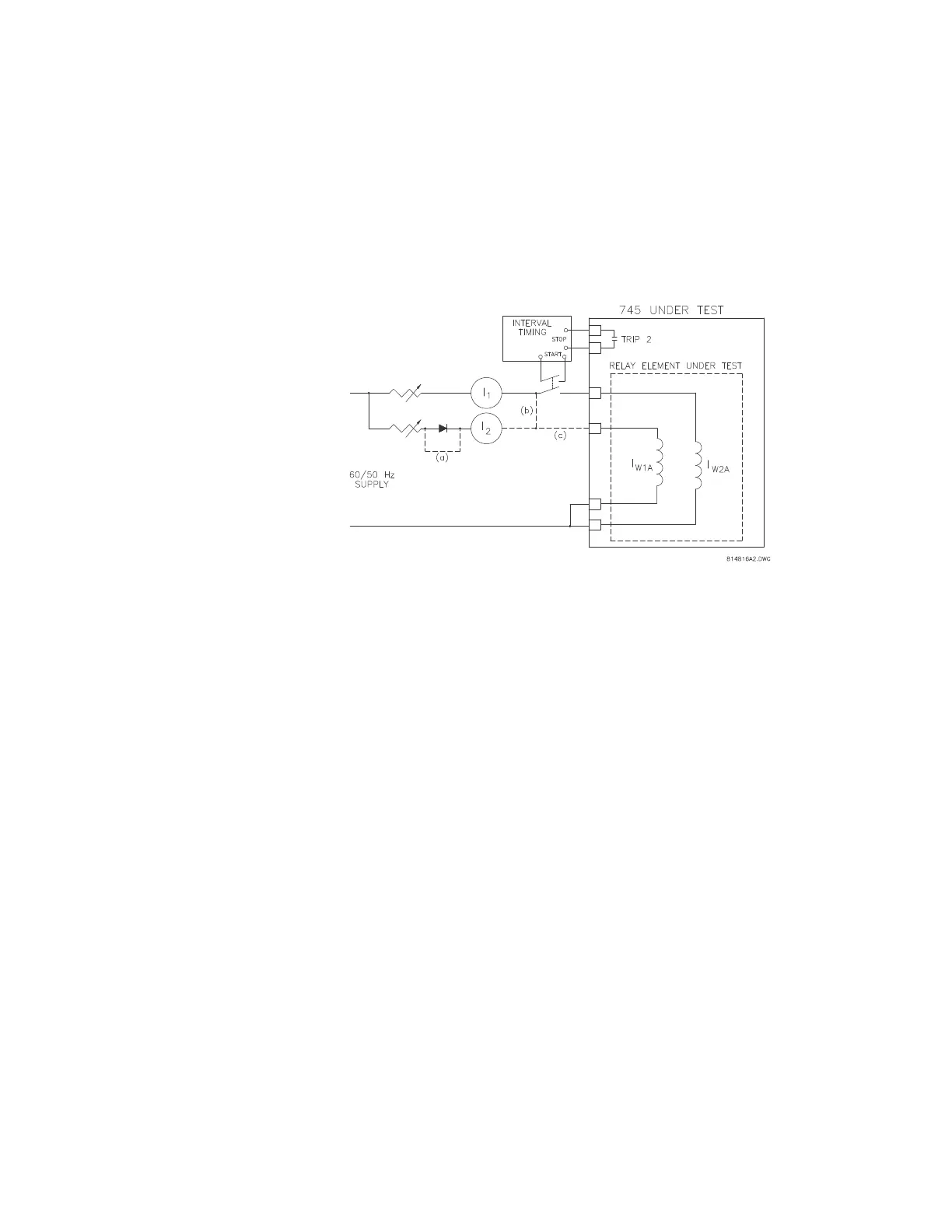
The simple test setup shown below can be used for the majority of tests. When the diode is
not shorted and the two currents are summed together prior to the switch, the composite
current contains the 2
nd
harmonic necessary to verify the 2
nd
harmonic restraint of the
harmonic restraint percent differential elements. With the diode shorted and the two
currents fed to separate relay inputs, the slope of the differential elements can be
measured. With only I
1
connected (with a return path) the pickup level of any element can
be measured.
FIGURE 7–1: Test setup