CHAPTER 7: COMMISSIONING PROTECTION SCHEMES
745 TRANSFORMER PROTECTION SYSTEM – INSTRUCTION MANUAL 7–25
7.5.4 Phase Time Overcurrent
7.5.4.1 Description
This procedure verifies that the phase time overcurrent element performance matches the
in-service settings. Since these elements can have any one of a multitude of timing curves,
a table of expected operating times versus applied current should be prepared prior to
testing the elements. Refer to Time Overcurrent Curves on page 5–59 for information on
timing curves.
If the relay elements are set for a “Linear” reset characteristic when measuring the
operating times, ensure that there is sufficient time between test current injections for the
element to reset fully; otherwise, erroneous timing measurements will be obtained. The
settings for these elements are found in the
S4 ELEMENTS PHASE OVERCURRENT
setpoints page.
7.5.4.2 Winding 1 Elements
To ensure that only the phase time overcurrent elements operate the trip relays (and any
other output relays) selected by the logic, disable all protection features except phase time
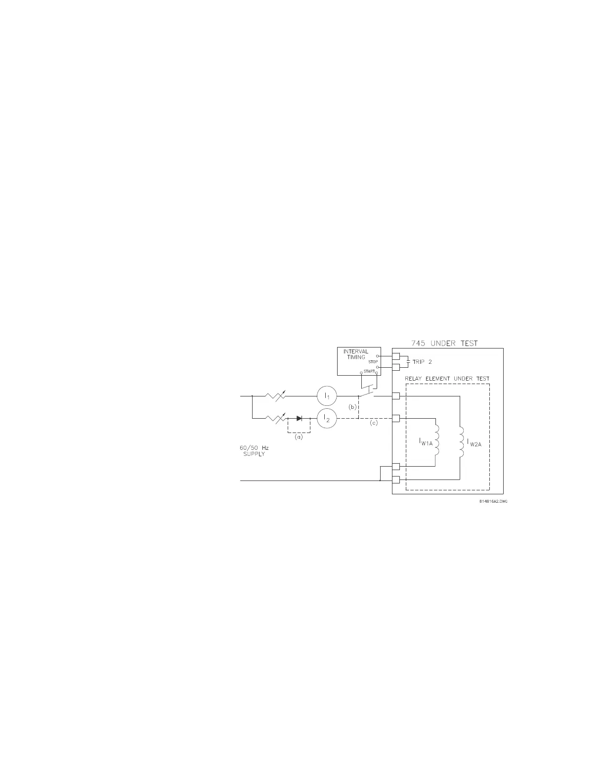
overcurrent. Use the general test setup shown below:
FIGURE 7–9: General test setup
Connect the current supply to terminals X = H1 and Y = G1 to test the winding 1 phase A
element. Monitor the appropriate output relays per the FlexLogic™ settings or from
assigned relay settings from Phase TOC.
7.5.4.3 Pickup Level
With the interval timer disabled, apply the current signal and increase its
magnitude slowly until the trip relay and all the selected auxiliary relays
operate.