7–36 745 TRANSFORMER PROTECTION SYSTEM – INSTRUCTION MANUAL
PROTECTION SCHEMES CHAPTER 7: COMMISSIONING
7.5.11.5 Winding 2 or 3 Element
Because the winding 2 and 3 elements can be set with completely different parameters
than the winding 1 elements, it is necessary to repeat the full set of tests described in this
section for each winding.
Note
Only two ground instantaneous overcurrent 1 elements can be in service
simultaneously.
Note
The blocking from logic input, if enabled, can be tested as described in earlier tests for
other elements.
7.5.12 Ground Instantaneous Overcurrent 2
The ground instantaneous overcurrent 2 elements are identical to the ground
instantaneous overcurrent 1 elements. Consequently, the same test procedure may be
used to verify their correct operation. Disable all protection features except ground
instantaneous overcurrent 2. Make the appropriate changes for the display indications
and output relays operated by the ground instantaneous overcurrent 2 elements.
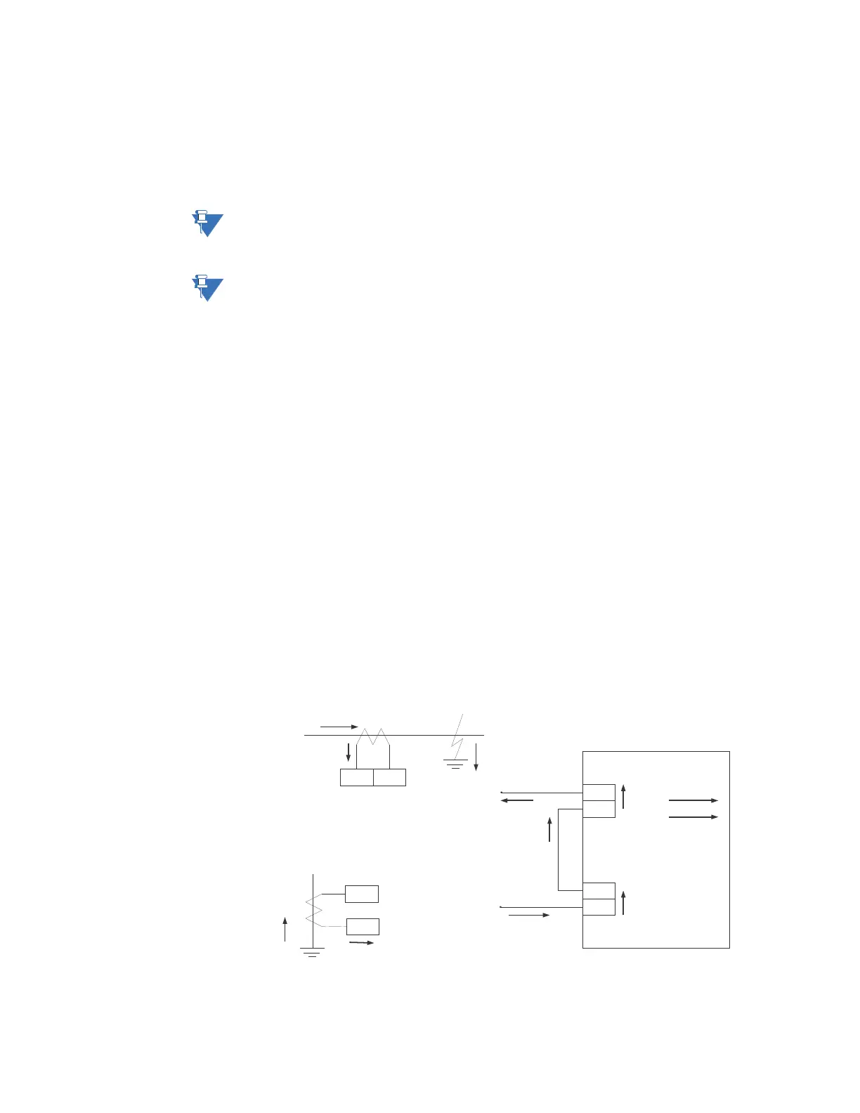
7.5.13 Restricted Ground Fault Polarity Test
This procedure verifies the correct wiring of field CTs (phase and ground) to the
corresponding phase and ground CT terminals on the relay for the purposes of the
restricted ground fault protection. The correct wiring is determined by the distribution of
fault current during external phase A to ground faults on wye-connected windings with
grounded neutral.
From the figure below, the I
f
fault current travels through the wye-grounded neutral as I
g
and can be simulated by injecting a single current into the phase A (W2) and G1/2
terminals.
FIGURE 7–10: Fault current distribution due to an external phase-to-ground fault on winding 2
H4 *
G4
H10 *
G10
AC source
50/60 Hz signal
Ig
3I0
I
3Io –Ig
I=0
RGF polarity wiring test
Ground CT
*
*
*
*
Phase A CT(W2)
745 relay
H4 *G4
G10
H10 *
G1/2 input
Phase A(W2)
Ig
If
Ig=I2
If=Ig=I1=I2
If=I1
I1
I2