GE Multilin C30 Controller System 1-3
1 GETTING STARTED 1.2 OVERVIEW
1
1.2OVERVIEW 1.2.1 INTRODUCTION TO THE UR
The GE Universal Relay (UR) series is a new generation of digital, modular, and multifunction equipment that is easily
incorporated into automation systems, at both the station and enterprise levels.
1.2.2 HARDWARE ARCHITECTURE
a) UR BASIC DESIGN
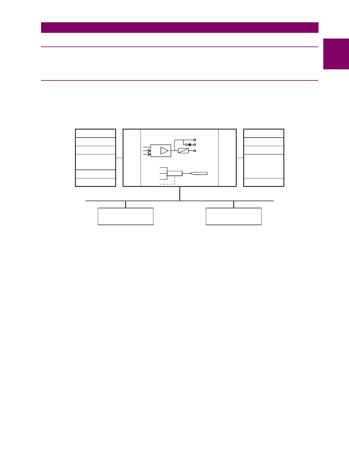
The UR is a digital-based device containing a central processing unit (CPU) that handles multiple types of input and output
signals. The UR device can communicate over a local area network (LAN) with an operator interface, a programming
device, or another UR device.
Figure 1–2: UR BLOCK DIAGRAM
The CPU module contains firmware that provides protection elements in the form of logic algorithms, as well as program-
mable logic gates, timers, and latches for control features.
Input elements accept a variety of analog or digital signals from the field. The UR isolates and converts these signals into
logic signals used by the relay.
Output elements convert and isolate the logic signals generated by the relay into digital or analog signals that can be used
to control field devices.
The software and unit are backwards-compatible with UR devices.
b) UR SIGNAL TYPES
The contact inputs and outputs are digital signals associated with connections to hard-wired contacts. Both ‘wet’ and ‘dry’
contacts are supported.
The virtual inputs and outputs are digital signals associated with UR-series internal logic signals. Virtual inputs include
signals generated by the local user interface. The virtual outputs are outputs of FlexLogic™ equations used to customize
the device. Virtual outputs can also serve as virtual inputs to FlexLogic equations.
The analog inputs and outputs are signals that are associated with transducers, such as Resistance Temperature Detec-
tors (RTDs).
The CT and VT inputs refer to analog current transformer and voltage transformer signals used to monitor AC power lines.
The UR-series relays support 1 A and 5 A CTs.
The remote inputs and outputs provide a means of sharing digital point state information between remote UR-series
devices. The remote outputs interface to the remote inputs of other UR-series devices. Remote outputs are FlexLogic oper-
ands inserted into IEC 61850 GSSE and GOOSE messages.
827822A3.CDR
Input elements
LAN
Programming
device
Operator
interface
Contact inputs Contact outputs
Virtual inputs
Virtual outputs
Analog inputs
Analog outputs
CT inputs
VT inputs
Input
status
table
Output
status
table
Pickup
Dropout
Operate
Protective elements
Logic Gates
Remote outputs
- IEC 61850
CPU module
Output elements
Remote inputs
Direct inputs Direct outputs