GE Multilin C30 Controller System 5-63
5 SETTINGS 5.2 PRODUCT SETUP
5
• DATA LOGGER MODE: This setting configures the mode in which the data logger will operate. When set to “Continu-
ous”, the data logger will actively record any configured channels at the rate as defined by the DATA LOGGER RATE. The
data logger will be idle in this mode if no channels are configured. When set to “Trigger”, the data logger will begin to
record any configured channels at the instance of the rising edge of the
DATA LOGGER TRIGGER source FlexLogic oper-
and. The data logger will ignore all subsequent triggers and will continue to record data until the active record is full.
Once the data logger is full a CLEAR DATA LOGGER command is required to clear the data logger record before a new
record can be started. Performing the
CLEAR DATA LOGGER command will also stop the current record and reset the
data logger to be ready for the next trigger.
• DATA LOGGER TRIGGER: This setting selects the signal used to trigger the start of a new data logger record. Any
FlexLogic operand can be used as the trigger source. The
DATA LOGGER TRIGGER setting only applies when the mode
is set to “Trigger”.
• DATA LOGGER RATE: This setting selects the time interval at which the actual value data will be recorded.
• DATA LOGGER CHNL 1(16): This setting selects the metering actual value that is to be recorded in Channel 1(16) of
the data log. The parameters available in a given relay are dependent on: the type of relay, the type and number of CT/
VT hardware modules installed, and the type and number of Analog Input hardware modules installed. Upon startup,
the relay will automatically prepare the parameter list. A list of all possible analog metering actual value parameters is
shown in Appendix A: FlexAnalog Parameters. The parameter index number shown in any of the tables is used to
expedite the selection of the parameter on the relay display. It can be quite time-consuming to scan through the list of
parameters via the relay keypad/display – entering this number via the relay keypad will cause the corresponding
parameter to be displayed.
• DATA LOGGER CONFIG: This display presents the total amount of time the Data Logger can record the channels not
selected to “Off” without over-writing old data.
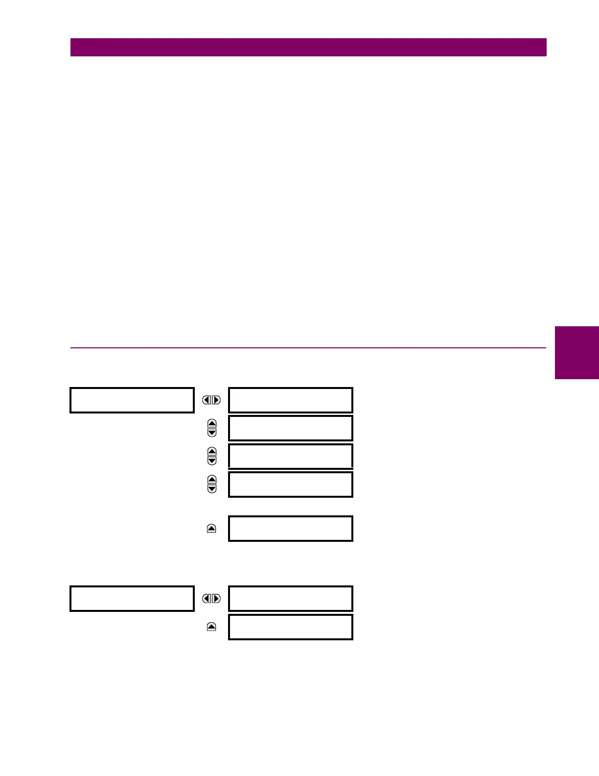
5.2.9 USER-PROGRAMMABLE LEDS
a) MAIN MENU
PATH: SETTINGS PRODUCT SETUP USER-PROGRAMMABLE LEDS
b) LED TEST
PATH: SETTINGS PRODUCT SETUP USER-PROGRAMMABLE LEDS LED TEST
When enabled, the LED test can be initiated from any digital input or user-programmable condition such as user-program-
mable pushbutton. The control operand is configured under the
LED TEST CONTROL setting. The test covers all LEDs,
including the LEDs of the optional user-programmable pushbuttons.
The test consists of three stages.
USER-PROGRAMMABLE
LEDS
LED TEST
See below
MESSAGE
TRIP & ALARM LEDS
See page 5–65.
MESSAGE
USER-PROGRAMMABLE
LED1
See page 5–65.
MESSAGE
USER-PROGRAMMABLE
LED2
↓
MESSAGE
USER-PROGRAMMABLE
LED48
LED TEST
LED TEST FUNCTION:
Disabled
Range: Disabled, Enabled.
MESSAGE
LED TEST CONTROL:
Off
Range: FlexLogic operand