GE Multilin C30 Controller System 3-1
3 HARDWARE 3.1 DESCRIPTION
3
3 HARDWARE 3.1DESCRIPTION 3.1.1 PANEL CUTOUT
a) HORIZONTAL UNITS
The C30 Controller System is available as a 19-inch rack horizontal mount unit with a removable faceplate. The faceplate
can be specified as either standard or enhanced at the time of ordering. The enhanced faceplate contains additional user-
programmable pushbuttons and LED indicators.
The modular design allows the relay to be easily upgraded or repaired by a qualified service person. The faceplate is
hinged to allow easy access to the removable modules, and is itself removable to allow mounting on doors with limited rear
depth.
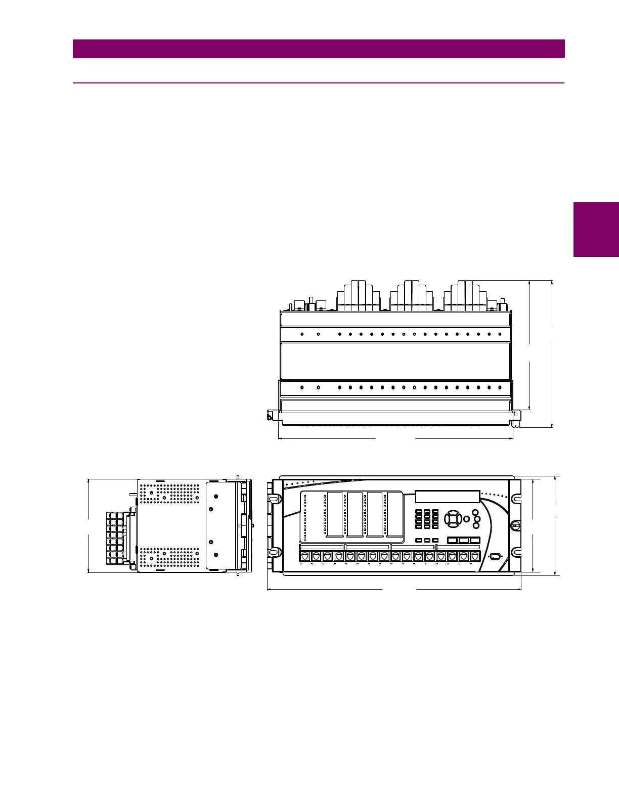
The case dimensions are shown below, along with panel cutout details for panel mounting. When planning the location of
your panel cutout, ensure that provision is made for the faceplate to swing open without interference to or from adjacent
equipment.
The relay must be mounted such that the faceplate sits semi-flush with the panel or switchgear door, allowing the operator
access to the keypad and the RS232 communications port. The relay is secured to the panel with the use of four screws
supplied with the relay.
Figure 3–1: C30 HORIZONTAL DIMENSIONS (ENHANCED PANEL)
17.56”
[446,02 mm]
9.687”
[246,05 mm]
11.016”
[279,81 mm]
7.460
[189,48 mm
6.960”
[176,78 mm]
19.040”
[483,62 mm]
6.995”
[177,67 mm]
842807A1.CDR