GE Multilin C30 Controller System 3-7
3 HARDWARE 3.1 DESCRIPTION
3
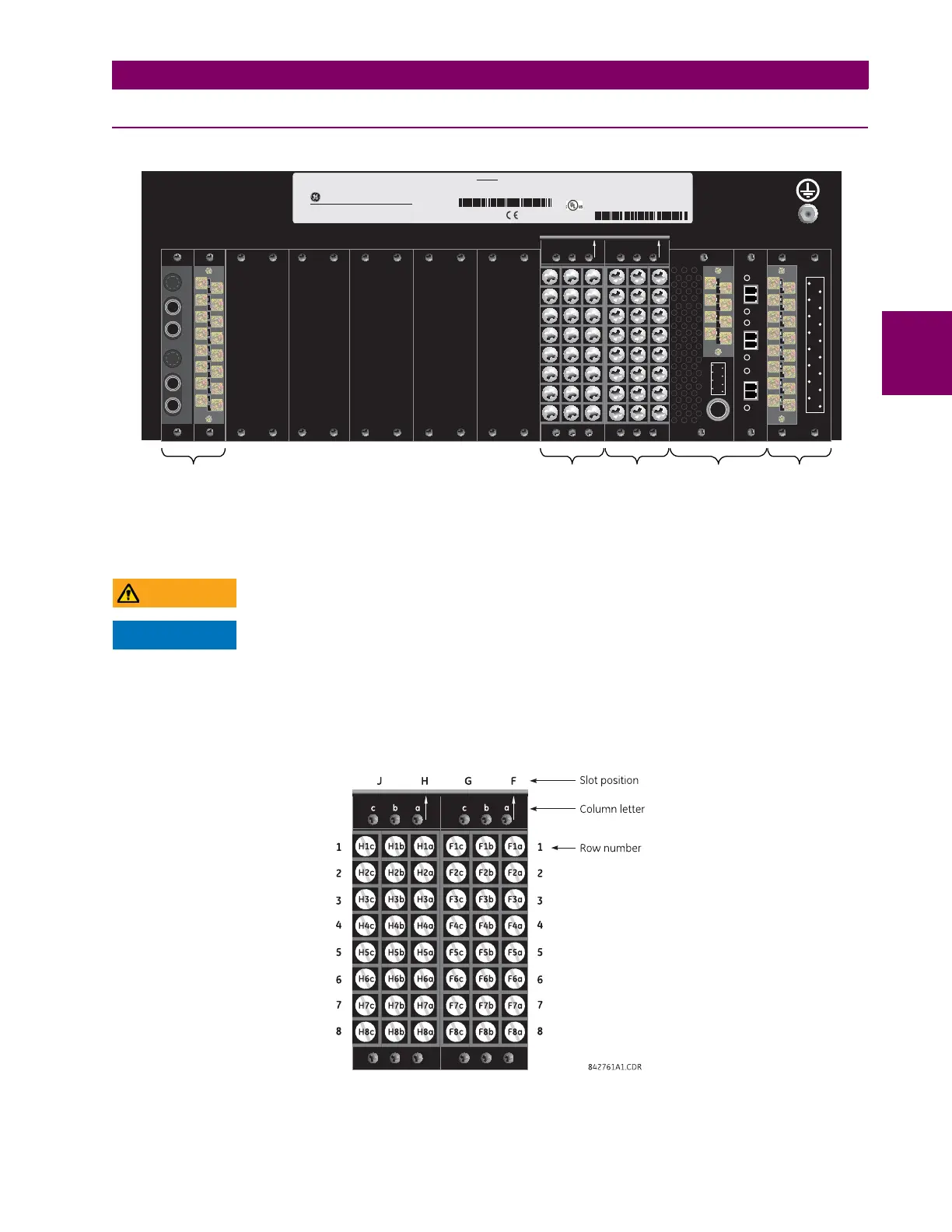
3.1.2 REAR TERMINAL LAYOUT
Figure 3–8: REAR TERMINAL VIEW
Do not touch any rear terminals while the relay is energized.
The small form-factor pluggable ports (SFPs) are pluggable transceivers. Do not use non-validated
transceivers or install validated transceivers in the wrong Ethernet slot, else damage can occur.
The relay follows a convention with respect to terminal number assignments which are three characters long assigned in
order by module slot position, row number, and column letter. Two-slot wide modules take their slot designation from the
first slot position (nearest to CPU module) which is indicated by an arrow marker on the terminal block. See the following
figure for an example of rear terminal assignments.
Figure 3–9: EXAMPLE OF MODULES IN F AND H SLOTS
834776A2.CDR
XW V U T S PN ML K J H DGF BR
8
4
7
3
6
2
5
1
b
8
4
7
3
6
2
5
1
a
abc abc
Tx1
Tx2
Rx1
Rx2
Tx1
Tx2
Optional
direct
input/output
module
CPU module
(T module shown)
Optional
contact
input/output
module
Optional
contact
input/output
module
Power
supply
module
4
3
2
1
4
3
2
1
b
a
IN
ACT3
LK3
ACT2
LK2
ACT1
LK1
®
®
Model:
Mods:
Wiring Diagram:
Inst. Manual:
Serial Number:
Firmware:
Mfg. Date:
PO Num:
Item Num:
C30D00HCHF8AH6AM6BP8BX7A
000
See manual
1609-0088
MAZB98000029
D
NOV 26, 2012
60001234.56
Control Power:
Contact Inputs:
Contact Outputs:
88-300V DC @ 35W / 77-265V AC @ 35VA
300V DC Max 10mA
Refer to Instruction Manual
RATINGS:
C30
- M A A B 9 7 0 0 0 0 9 9 -
Controller
GE Multilin
LISTED
52TL
IND.CONT. EQ.
E83849
- M A A B 9 7 0 0 0 0 9 9 -