5-114 C30 Controller System GE Multilin
5.6 CONTROL ELEMENTS 5 SETTINGS
5
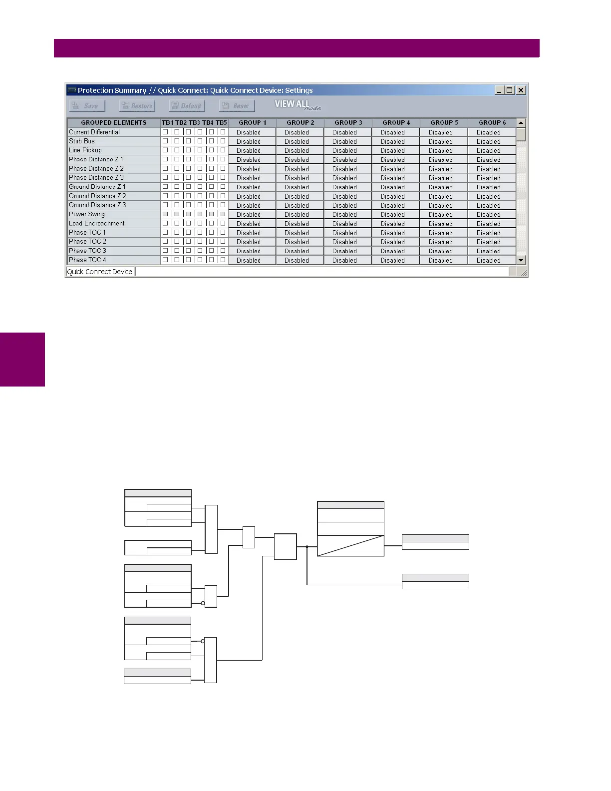
Figure 5–38: TRIP BUS FIELDS IN THE PROTECTION SUMMARY
The following settings are available.
• TRIP BUS 1 BLOCK: The trip bus output is blocked when the operand assigned to this setting is asserted.
• TRIP BUS 1 PICKUP DELAY: This setting specifies a time delay to produce an output depending on how output is
used.
• TRIP BUS 1 RESET DELAY: This setting specifies a time delay to reset an output command. The time delay should be
set long enough to allow the breaker or contactor to perform a required action.
• TRIP BUS 1 INPUT 1 to TRIP BUS 1 INPUT 16: These settings select a FlexLogic operand to be assigned as an input
to the trip bus.
• TRIP BUS 1 LATCHING: This setting enables or disables latching of the trip bus output. This is typically used when
lockout is required or user acknowledgement of the relay response is required.
• TRIP BUS 1 RESET: The trip bus output is reset when the operand assigned to this setting is asserted. Note that the
RESET OP operand is pre-wired to the reset gate of the latch, As such, a reset command the front panel interface or via
communications will reset the trip bus output.
Figure 5–39: TRIP BUS LOGIC
***
SETTINGS
=Off
TRIP BUS 1 INPUT 2
=Off
TRIP BUS 1 INPUT 1
=Off
TRIP BUS 1 INPUT 16
OR
SETTINGS
= Enabled
TRIP BUS 1
FUNCTION
=Off
TRIP BUS 1 BLOCK
AND
AND
Latch
S
R
Non-volatile,
set-dominant
SETTINGS
= Enabled
TRIP BUS 1
LATCHING
=Off
TRIP BUS 1 RESET
FLEXLOGIC OPERAND
TRIP BUS 1 PKP
OR
SETTINGS
TRIP BUS 1 PICKUP
DELAY
TRIP BUS 1 RESET
DELAY
T
PKP
T
RST
FLEXLOGIC OPERAND
RESET OP
FLEXLOGIC OPERAND
TRIP BUS 1 OP
842023A1.CDR