GE Multilin C30 Controller System 5-129
5 SETTINGS 5.6 CONTROL ELEMENTS
5
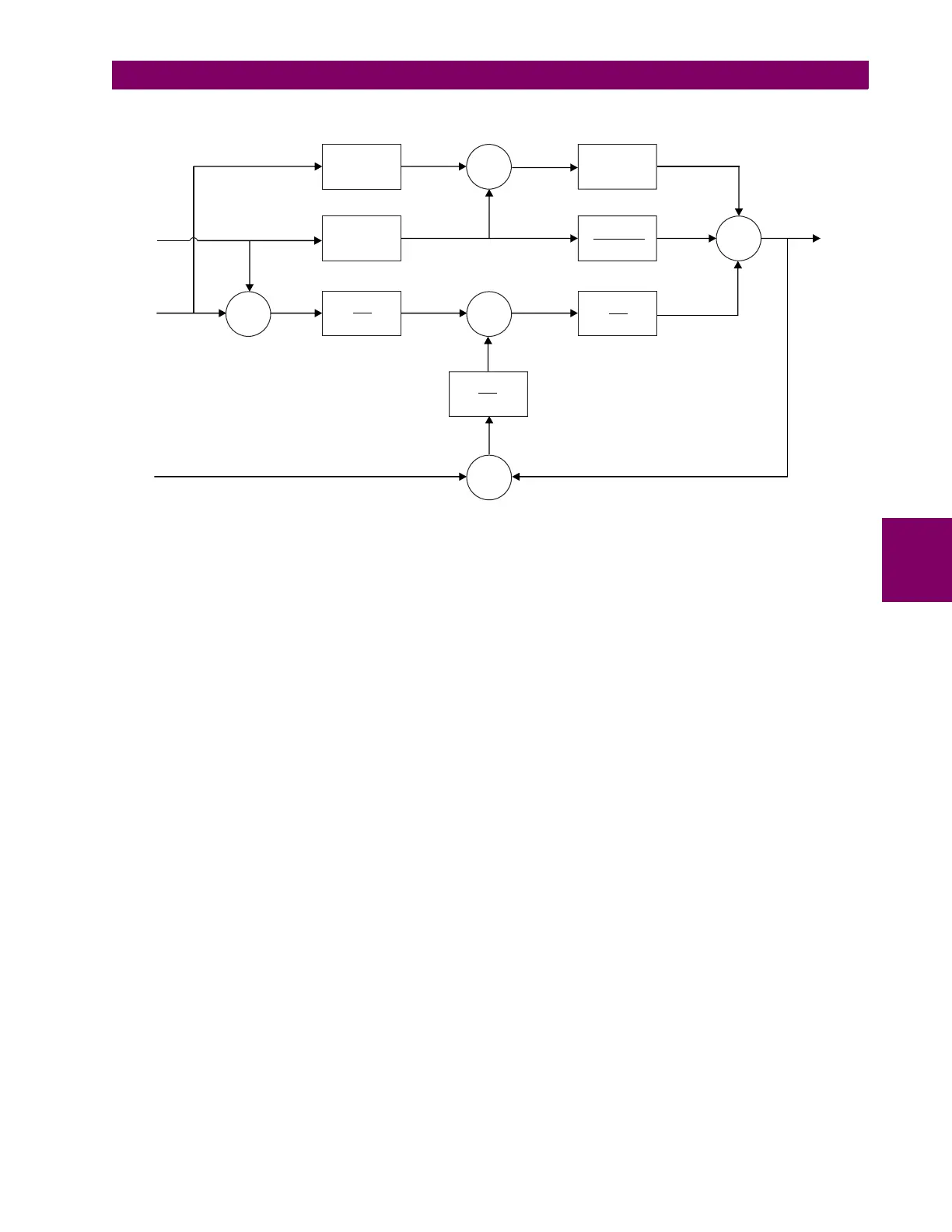
A general form of a PID regulator in the s domain is shown below.
Figure 5–48: PID BLOCK DIAGRAM
The following terms apply to the block diagram:
• y is the process signal
• r is the setpoint signal
• w is the tracking signal
• u is the regulator output
• K is the proportional gain
• b is the setpoint weighting
•T
d
is the derivative time constant
• N is the derivative limit
•T
i
is the integral time constant
•T
t
is the anti-windup time constant
• s is the domain
In discrete form, the equations for the regulator are:
(EQ 5.1)
Where T
S
is the sampling time and AW is a flag which enables anti-windup. The incremental form of the above equation is:
(EQ 5.2)
Where:
y
r
w
+
-
e
K
T
i
+
+
1
s
1
T
t
+
-
i
+
+
+
d
u
sKT
d
1+sT /N
d
+
-1
b
+
p
K
832031A1.cdr
ek() rk() yk()–=
pk() Kbrk() yk()–()=
dk()
T
d
T
d
NT
S
+
------------------------
dk 1–()×
kT
d
N
T
d
NT
S
+
------------------------
yk() yk 1–()–()×–=
uk() pk() ik() dk()++=
ik 1+()ik()
KT
S
ek()
T
i
-----------------------
T
S
T
t
------
wk() uk()–()AW××
++=
Du k() uk() uk 1–()–=
Dp k() Di k() Dd k()++=