DigitalFlow™ XMT868i Startup Guide 13
Chapter 1. Installation
1.7.5b Wiring an Alarms Option Card
Each alarms option card includes two or four general-purpose Form C relays (designated as A, B, C and D).
The maximum electrical ratings for the relays are listed in Chapter 4, Specifications. Each of the alarm relays can be
wired as either Normally Open (NO) or Normally Closed (NC).
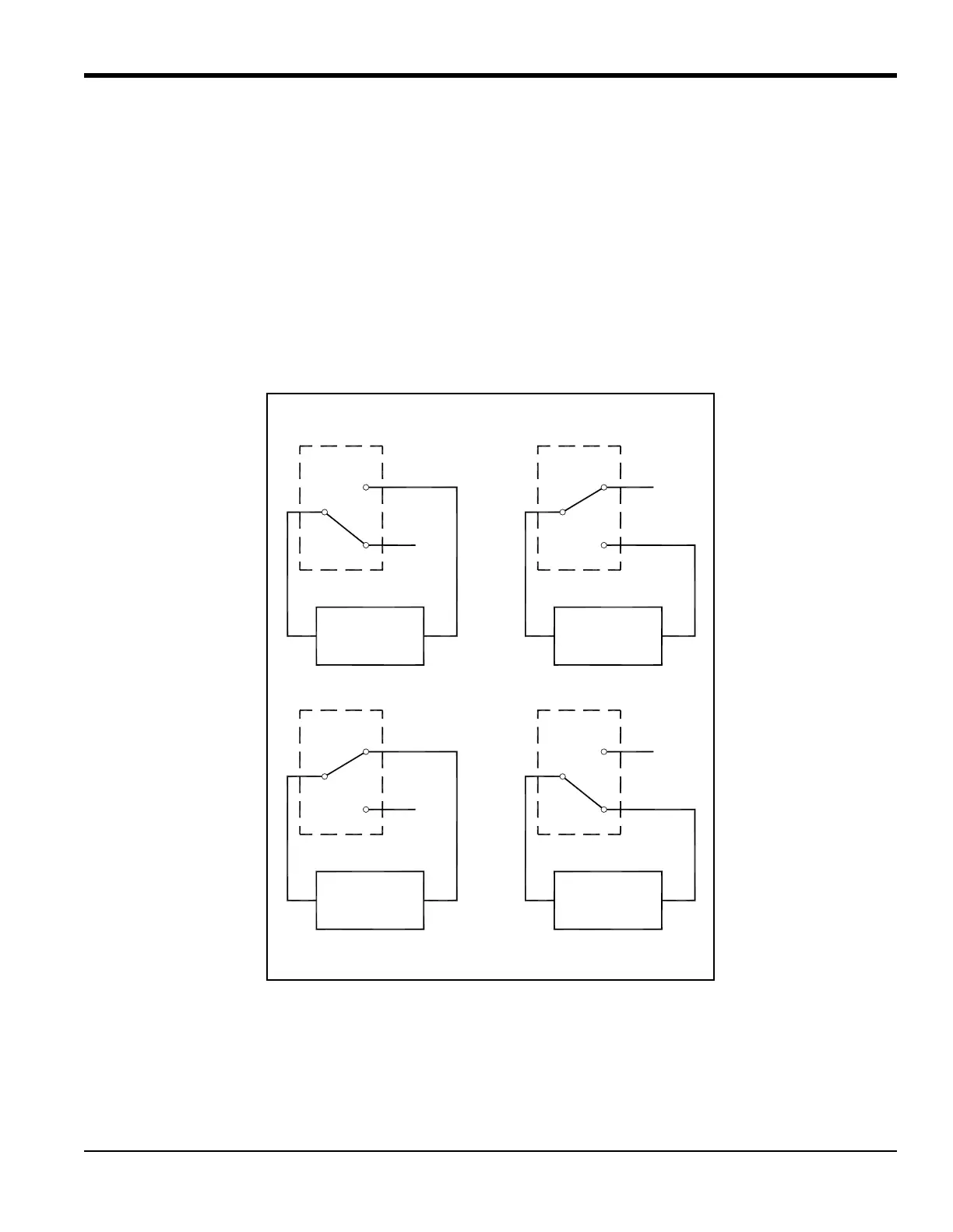
In setting up an alarm relay, it may be wired for either conventional or fail-safe operation. In fail-safe mode, the alarm
relay is constantly energized, except when it is triggered or a power failure or other interruption occurs. See Figure 4
below for the operation of a normally open alarm relay in both conventional and fail-safe mode.
Connect each alarm relay in accordance with the wiring instructions shown on the label inside the rear cover (see
Figure 3 on page 6 and Figure 11 on page 24).
Figure 4: Conventional and Fail-Safe Operation
C
NO
NC NC
C
NO
NC NC
C
NO
C
NO
Conventional
not triggered not triggered
Fail-Safe
triggered or power failure
Fail-Safe
triggered
Conventional
ALARM
MONITORING
DEVICE DEVICE
MONITORING
ALARM
DEVICE
MONITORING
ALARM
DEVICE
MONITORING
ALARM

 Loading...


