DigitalFlow™ XMT868i Startup Guide 15
Chapter 1. Installation
1.7.5d Wiring a Totalizer and Frequency Output Option Card
Each totalizer and frequency output option card provides two or four outputs (designated as A, B, C, and D).
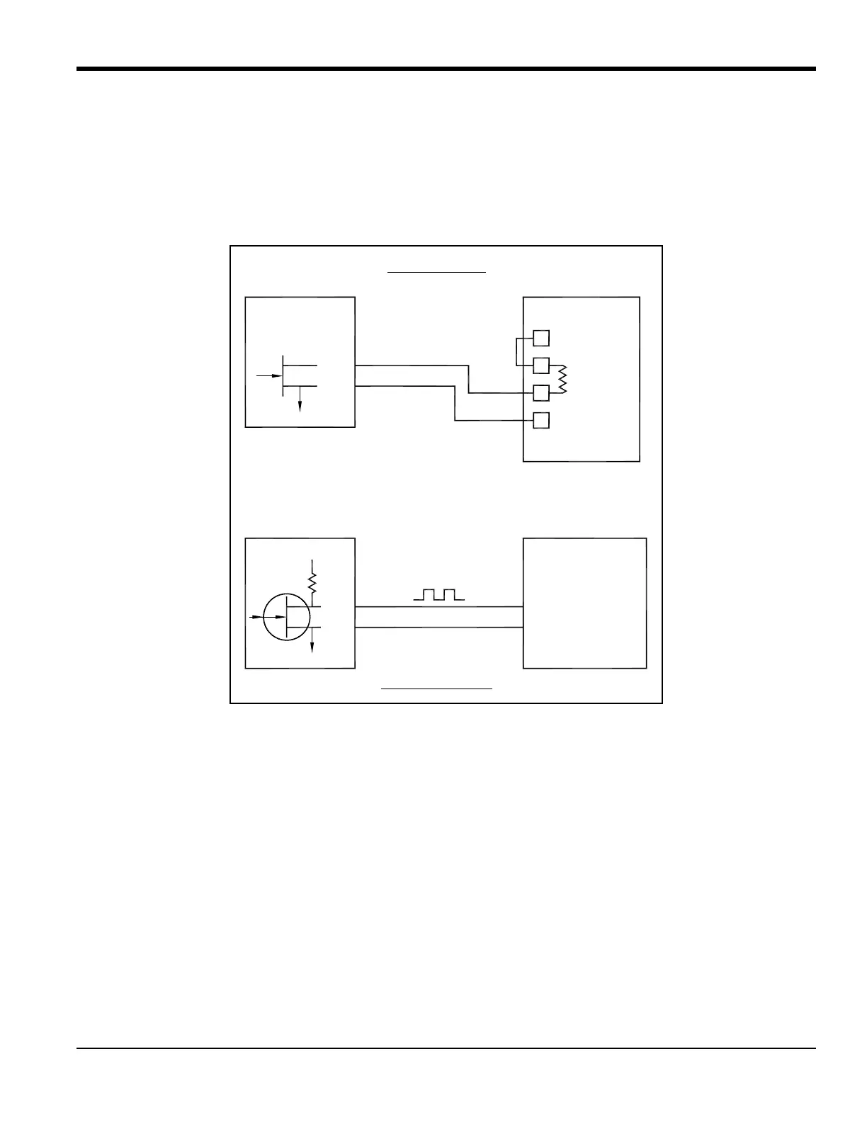
Wire this option card in accordance with the connections shown on the label in the rear cover (see Figure 3 on page 6
and Figure 11 on page 24). Figure 6 below shows sample wiring diagrams of a totalizer output circuit and a frequency
output circuit. Refer to Electrical Specifications on page 61 for the load and voltage requirements.
Figure 6: Totalizer and Frequency Output Wiring
OUT
RTN
IN
Common
Load
Volts -
(Common)
Volts +
(Int. Pwr. Sup.)
OUT
RTN
+5V
200
:
Model XMT868 Pulse Counter
Totalizer Output
Frequency CounterModel XMT868
Frequency Output