GEK-106310AB F650 Digital Bay Controller 7-7
7 IEC 61850 PROTOCOL 7.2 IEC 61850 PROFILE FOR F650
7
7.2.1.1 SCOPE AND OUTLINE OF IEC 61850
Parts 3, 4, and 5 of the standard start by identifying the general and specific functional requirements for communications in
a substation. These requirements are then used as forcing functions to aid in the identification of the services and data
models needed, application protocol required, and the underlying transport, network, data link, and physical layers that will
meet the overall requirements.
The major architectural construct that 61850 adopts is that of "abstracting" the definition of the data items and the services,
that is, creating data items/objects and services that are independent of any underlying protocols. The abstract definitions
then allow "mapping" of the data objects and services to any other protocol that can meet the data and service
requirements.
The definition of the abstract services is found in part 7.2 of the standard and the abstraction of the data objects (referred to
as Logical Nodes) is found in part 7.4.
In as much as many of the data objects are made up of common pieces (such as Status, Control, Measurement,
Substitution), the concept of "Common Data Classes" or "CDC" was developed which defined common building blocks for
creating the larger data objects. The CDC elements are defined in part 7.3.
Given the data and services abstract definitions, the final step was one of "mapping" the abstract services into an actual
protocol. Section 8.1 defines the mapping of the abstract data object and services onto the Manufacturing Messaging
Specification - MMS2 and sections 9.1 and 9.2 define the mapping of the Sample Measured Values (unidirectional point-to-
point and bi-directional multipoint accordingly) onto an Ethernet data frame. The 9.2 document defines what has become
known as the Process Bus.
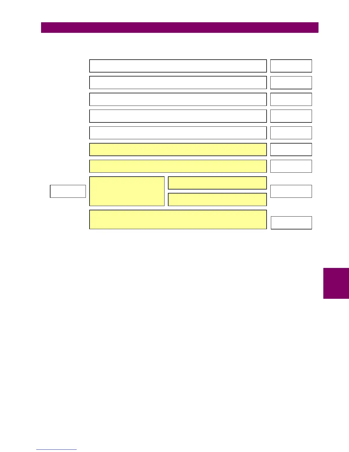
Basic principles Part 1
Glossary
Part 2
General Requirements Part 3
System and project management Part 4
Communication requirements Part 5
Substation Automation System Configuration Part 6
Basic Communication Structure (4 sections) Part 7
1.1 Sampled Measured Values
Part 9 Part 8
Mapping to Ethernet
Mapping to MMS and
Ethernet
Conformance testing
Part 10