GEK-106310AB F650 Digital Bay Controller 5-19
5 SETTINGS 5.2 PRODUCT SETUP
5
5.2.6.3 DEMAND FUNCTION MEASURES AND STATES
Demand values are available at Actual > Metering > Primary Values > Demand.
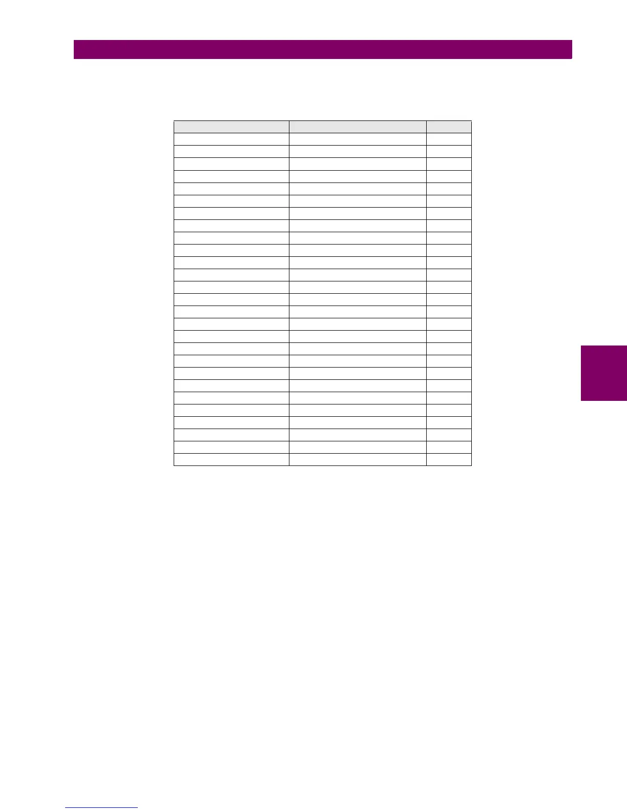
Table 5–18: DEMAND MEASURES
Demand measurements for current values are as follows:
DEMAND IX This is the demanded value every minute or every integration period, depending on the
selected settings.
DEMAND IX MAX Demanded maximeter; it stores the Maximum demand value until a demand reset is
issued.
DEMAND IX DATE Date of the Maximum demand value
Being X the phase considered in each case.
Demand measurements for power values are as follows:
DEMAND Y This is the demanded value every minute or every integration period, depending on the
selected settings
DEMAND Y MAX Demanded maximeter; it stores the Maximum demand value until a demand reset is
issued.
DEMAND Y DATE Date of the Maximum demand value.
Being Y the power considered in each case.
NAME DEFAULT VALUE STEP
DEMAND IA 0.000 KA
DEMAND IA MAX 0.000 KA
DEMAND IA DATE 01-Jan-2000 00:00:00.000
DEMAND IB 0.000 KA
DEMAND IB MAX 0.000 KA
DEMAND IB DATE 01-Jan-2000 00:00:00.000
DEMAND IC 0.000 KA
DEMAND IC MAX 0.000 KA
DEMAND IC DATE 01-Jan-2000 00:00:00.000
DEMAND IG 0.000 KA
DEMAND IG MAX 0.000 KA
DEMAND IG DATE 01-Jan-2000 00:00:00.000
DEMAND ISG 0.000 KA
DEMAND ISG MAX 0.000 KA
DEMAND ISG DATE 01-Jan-2000 00:00:00.000
DEMAND I2 0.000 KA
DEMAND I2 MAX 0.000 KA
DEMAND I2 DATE 01-Jan-2000 00:00:00.000
DEMAND W 0.000 MW
DEMAND W MAX 0.000 MW
DEMAND W DATE 01-Jan-2000 00:00:00.000
DEMAND VAR PWR 0.000 MVAr
DEMAND VAR MAX 0.000 MVAr
DEMAND VAR DATE 01-Jan-2000 00:00:00.000
DEMAND VA PWR 0.000 MVA
DEMAND VA MAX 0.000 MVA
DEMAND VA DATE 01-Jan-2000 00:00:00.000