GEK-106310AB F650 Digital Bay Controller 3-1
3 HARDWARE 3.1 MODULE DESCRIPTION
3
3 HARDWARE 3.1MODULE DESCRIPTION
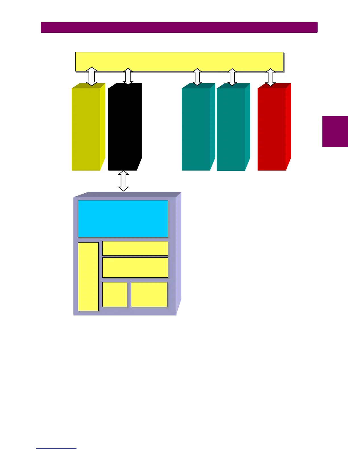
Figure 3–1: BLOCK DIAGRAM
F650 units incorporate the following modules:
• Power supply, which can be simple or redundant, depending on the selected model
• Front module with alphanumerical (4 x 20) or optional graphical (16 x 40 characters) display. It includes the bus
on its rear, which communicates with the rest of modules via a high speed CAN bus.
• Transformers module with 5 current transformers and 4 voltage transformers
• CPU including a powerful DSP for measure processing as well as synchronous and asynchronous communication
accessories.
• Input/Output module included in basic unit
• Optionally, a second I/O module can be added.
H
H
i
i
g
g
h
h
S
S
p
p
e
e
e
e
d
d
s
s
e
e
r
r
i
i
a
a
l
l
C
C
A
A
N
N
B
B
u
u
s
s
A
A
n
n
a
a
l
l
o
o
g
g
i
i
n
n
p
p
u
u
t
t
s
s
V
V
T
T
s
s
a
a
n
n
d
d
C
C
T
T
s
s
CPU
Module
Digital
I/O
Power
Supply
Optional
Digital
I/O
S
S
h
h
u
u
t
t
t
t
l
l
e
e
k
k
e
e
y
y
L
L
o
o
c
c
a
a
l
l
/
/
R
R
e
e
m
m
o
o
t
t
e
L
L
E
E
D
D
s
s
SCREEN
K
K
e
e
y
y
p
p
a
a
d
d
R
R
S
S
2
2
3
3
2
2