GEK-106310AB F650 Digital Bay Controller 5-29
5 SETTINGS 5.3 SYSTEM SETUP
5
5.3.4 SWITCHGEAR
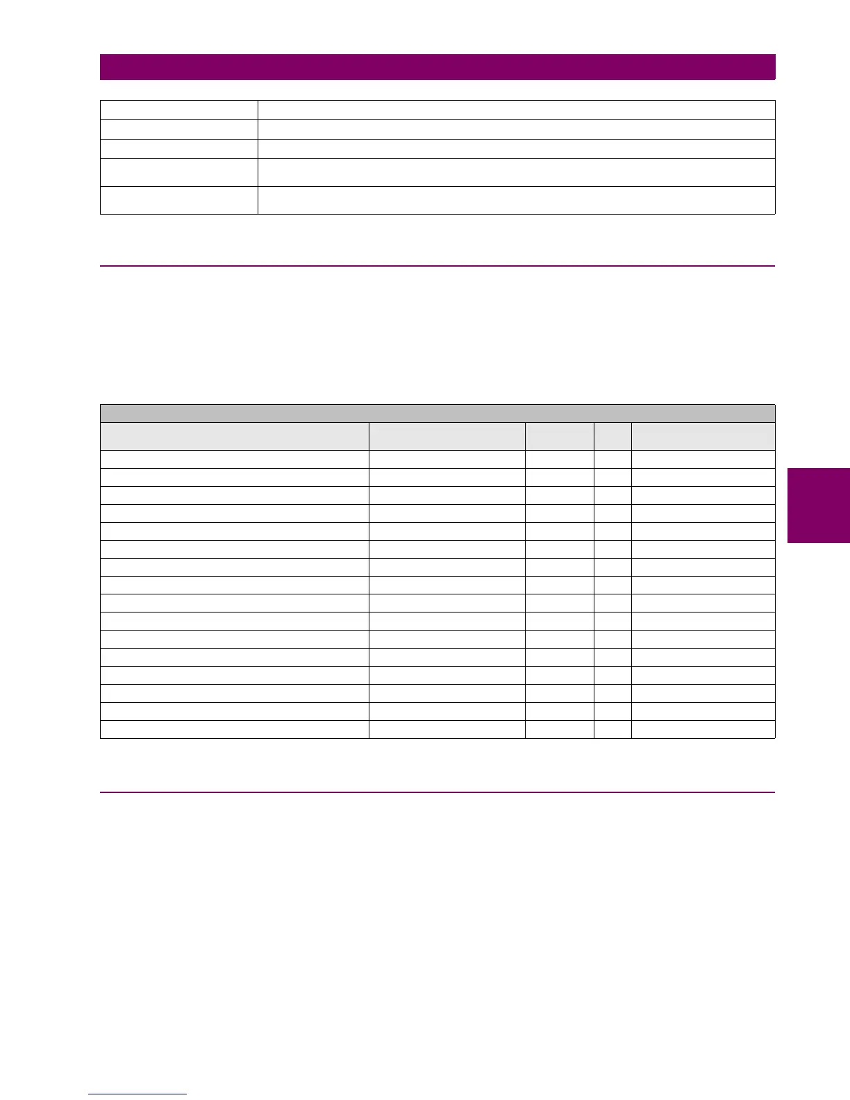
There is the possibility to enable or disable the generation of internal signals for the different elements (protection, control,
inputs and outputs, switchgear) available in the device.
The configuration of snapshot events for each switchgear (enable or disable) can be selected at Setpoint > System Setup
> Switchgear.
Table 5–26: SWITCHGEAR SETTINGS
5.3.5 TIME SETTINGS
The date and time can be synchronized a known time using the SNTP protocol or IRIG-B protocol (when it provides UTC
Time) and the TIME SETTINGS allow setting the date and time provided by these protocols to the proper local time on the
Real Time Clock.
When there is no SNTP protocol enabled or IRIG-B protocol is not set to UTC Time, the TIME SETTINGS are not used in
the Real Time Clock but are still used to calculate the UTC Time (i.e., for the IEC61850 protocol), but its behavior is not
assumed correct in several critical hour changes because of Daylight Savings Time getting effective. In these configuration
cases, it is recommended to disable Daylight Savings Time.
Table 5–27: TIME SETTINGS
(KI)
2
t PHASE A Accumulated (KI)
2
t value for phase A ((KI)
2
t Counter for Phase A)
(KI)
2
t PHASE B Accumulated (KI)
2
t value for phase B ((KI)
2
t Counter for Phase B)
(KI)
2
t PHASE C Accumulated (KI)
2
t value for phase C ((KI)
2
t Counter for Phase C)
BKR OPENING TIME Maximum breaker Opening time. This signal is configured at Setpoint > Relay Configuration
>Switchgear in the number of switchgear corresponding to the breaker selection
BKR CLOSING TIME Maximum breaker Closing time. This signal is configured at Setpoint > Relay Configuration
>Switchgear in the number of switchgear corresponding to the breaker selection
SETPOINT > SYSTEM SETUP > SWITCHGEAR
SETTING DESCRIPTION NAME DEFAULT
VALUE
STEP RANGE
Snapshot Event generation for switchgear #1 Snapshot Events SWGR 1 DISABLED N/A [DISABLED – ENABLED]
Snapshot Event generation for switchgear #2 Snapshot Events SWGR 2 DISABLED N/A [DISABLED – ENABLED]
Snapshot Event generation for switchgear #3 Snapshot Events SWGR 3 DISABLED N/A [DISABLED – ENABLED]
Snapshot Event generation for switchgear #4 Snapshot Events SWGR 4 DISABLED N/A [DISABLED – ENABLED]
Snapshot Event generation for switchgear #5 Snapshot Events SWGR 5 DISABLED N/A [DISABLED – ENABLED]
Snapshot Event generation for switchgear #6 Snapshot Events SWGR 6 DISABLED N/A [DISABLED – ENABLED]
Snapshot Event generation for switchgear #7 Snapshot Events SWGR 7 DISABLED N/A [DISABLED – ENABLED]
Snapshot Event generation for switchgear #8 Snapshot Events SWGR 8 DISABLED N/A [DISABLED – ENABLED]
Snapshot Event generation for switchgear #9 Snapshot Events SWGR 9 DISABLED N/A [DISABLED – ENABLED]
Snapshot Event generation for switchgear #10 Snapshot Events SWGR 10 DISABLED N/A [DISABLED – ENABLED]
Snapshot Event generation for switchgear #11 Snapshot Events SWGR 11 DISABLED N/A [DISABLED – ENABLED]
Snapshot Event generation for switchgear #12 Snapshot Events SWGR 12 DISABLED N/A [DISABLED – ENABLED]
Snapshot Event generation for switchgear #13 Snapshot Events SWGR 13 DISABLED N/A [DISABLED – ENABLED]
Snapshot Event generation for switchgear #14 Snapshot Events SWGR 14 DISABLED N/A [DISABLED – ENABLED]
Snapshot Event generation for switchgear #15 Snapshot Events SWGR 15 DISABLED N/A [DISABLED – ENABLED]
Snapshot Event generation for switchgear #16 Snapshot Events SWGR 16 DISABLED N/A [DISABLED – ENABLED]