5-70 F650 Digital Bay Controller GEK-106310AB
5.4 PROTECTION ELEMENTS 5 SETTINGS
5
5.4.7 NEGATIVE SEQUENCE CURRENT
The Negative sequence menu incorporates the Negative sequence time overcurrent (46P) element:
5.4.7.1 NEGATIVE SEQUENCE OVERCURRENT ELEMENT (46P)
Negative Sequence TOC is an overcurrent protection element that uses the fundamental phasor of the negative sequence
current as input magnitude, calculated from the phase currents. This element can be used for detecting load unbalance in
the system, and for open phase conditions (fallen or broken conductor). The trip can be time delayed by a curve selectable
by setting. The reset can be instantaneous or linear.
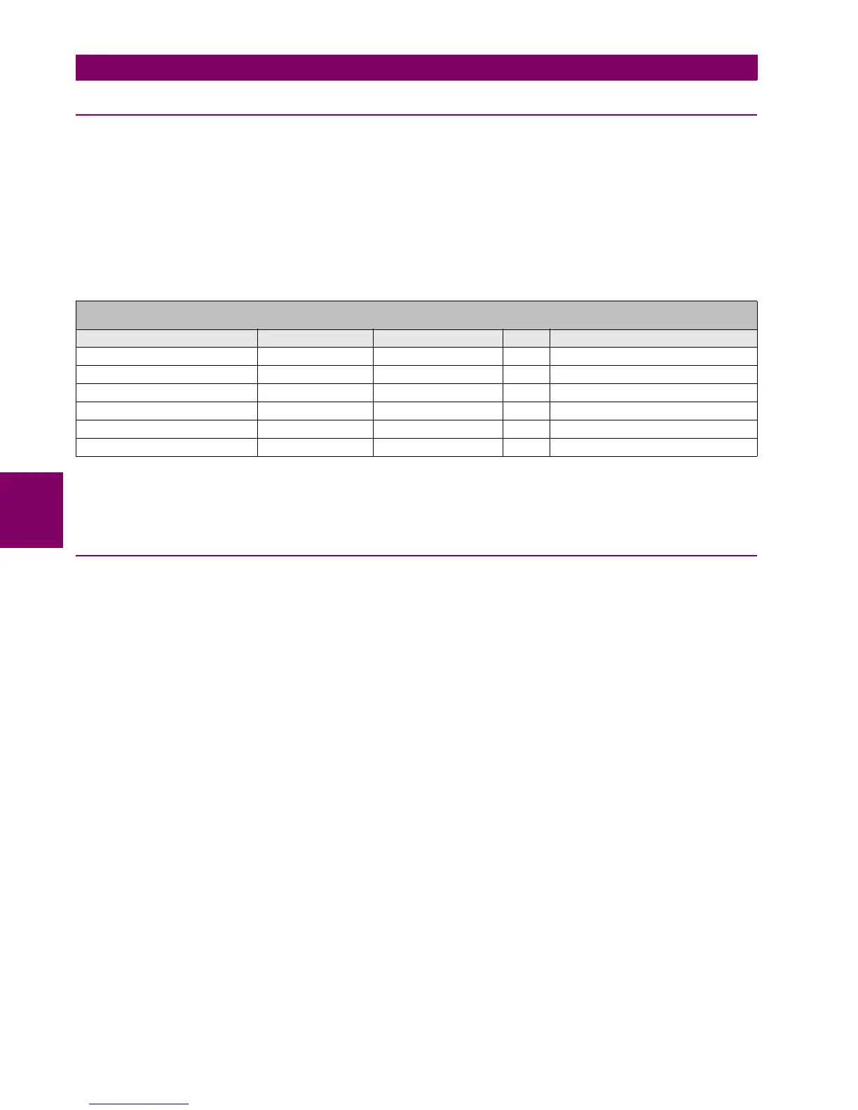
Table 5–63: NEGATIVE SEQUENCE TOC ELEMENT SETTINGS
The snapshot event setting enables or disables the snapshot event generation for this element.
5.4.8 VOLTAGE ELEMENTS
The F650 incorporates the following voltage elements:
• Phase undervoltage (27P)
• Phase overvoltage (59P)
• Neutral overvoltage (59NH/59NL)
• Negative sequence overvoltage (47)
• Auxiliary overvoltage (59X)
• Auxiliary undervoltage (27X)
These protection elements can be used in multiple applications, such as:
Undervoltage protection: for induction motor load types, where a voltage dip can cause an increase of the consumed
current. Element 27P (phase undervoltage) can be used to issue a trip or an alarm.
Transfer Schemes: in the event of an undervoltage condition, we can use the 27P element (phase undervoltage) to send a
signal that will transfer load to another power source.
Undervoltage elements can be set to operate with definite time or with an inverse time curve. If the element is set as
definite time, it will operate when voltage remains under the set value during the set period of time. This period can be set
from 0s to 900.00 s in steps of 10ms.
SETPOINT > PROTECTION ELEMENTS > NEGATIVE SEQUENCE CURRENT > NEGATIVE SEQUENCE TOC >
NEGATIVE SEQUENCE TOC 1> NEGATIVE SEQUENCE TOC 2 > NEGATIVE SEQUENCE TOC 3
SETTING DESCRIPTION NAME DEFAULT VALUE STEP RANGE
Function permission Function DISABLED N/A [DISABLED – ENABLED]
Pickup level Pickup Level 1.00 0.01 A [0.05 : 160.00]
Curve shape Curve IEEE Ext Inv N/A [See list of curves]
Time Dial TD Multiplier 1.00 0.01 s [0.00 : 900.00]
Reset type Reset INSTANTANEOUS N/A [INSTANTANEOUS – LINEAR]
Snapshot Event generation Snapshot Events ENABLED N/A [DISABLED – ENABLED]