EasyManuals Logo

GE F650 User Manual

GE F650
801 pages
To Next Page IconTo Next Page
To Previous Page IconTo Previous Page
Page #498 background imageLoading...
Page #498 background image
GEK-106310AB F650 Digital Bay Controller 10-13
10 COMMISSIONING 10.10 CONNECTIONS FOR TESTING PROTECTION ELEMENTS
10
10.10CONNECTIONS FOR TESTING PROTECTION ELEMENTS
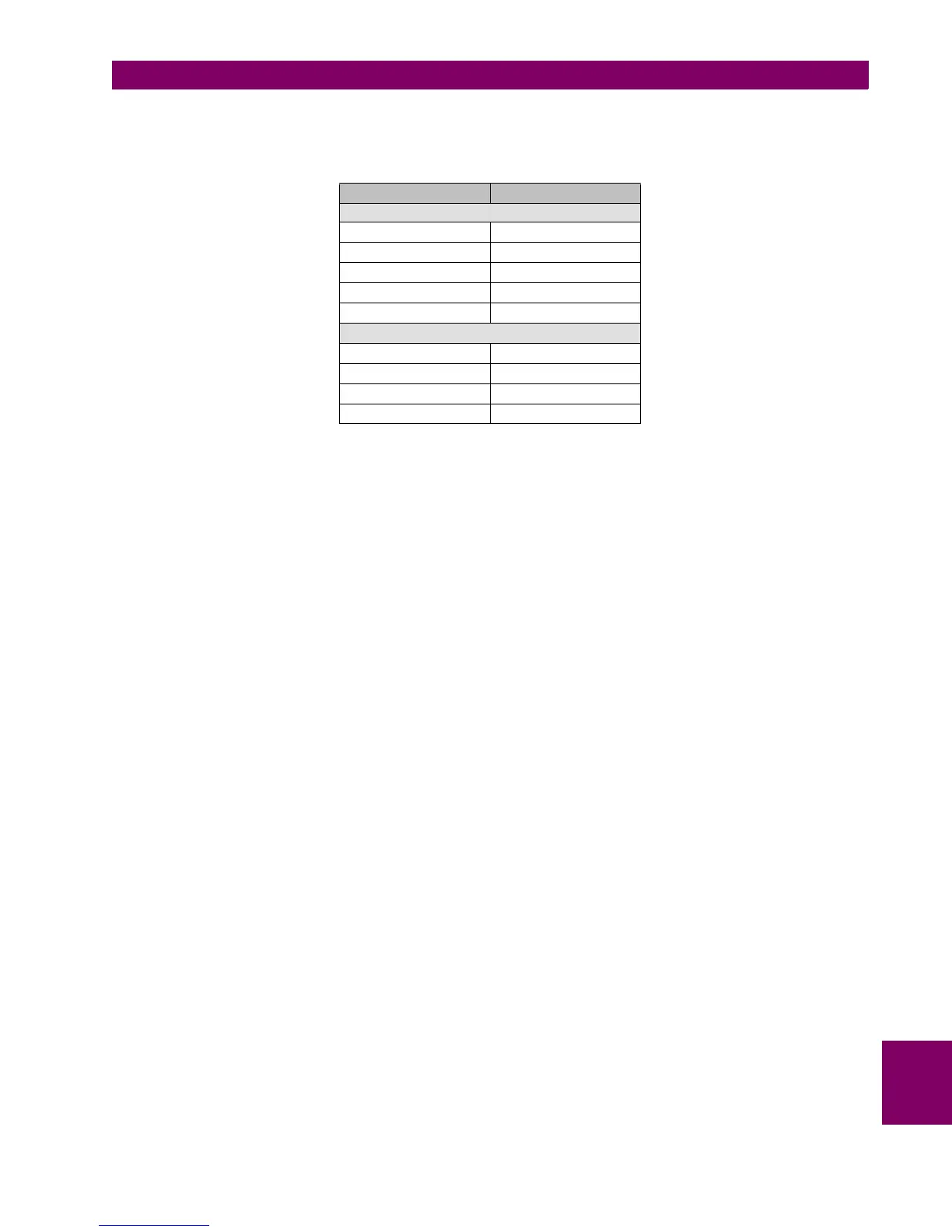
Connect current sources to the relay according to the wiring diagram. Current and voltage input terminals are as follows:
PHASE CONNECTIONS
Current
IA B1-B2
IB B3-B4
IC B5-B6
IG B9-B10
ISG B11-B12
Voltage
VI A5-A6
VII A7-A8
VIII A9-A10
VX A11-A12

Table of Contents

Other manuals for GE F650

Questions and Answers:

Question and Answer IconNeed help?

Do you have a question about the GE F650 and is the answer not in the manual?

GE F650 Specifications

General IconGeneral
ModelF650
CategoryController
Frequency50/60 Hz
DisplayLCD
TypeFeeder Protection Relay
ApplicationFeeder Protection and Control
Communication ProtocolsDNP3, Modbus, IEC 61850
Protection FunctionsOvercurrent, Earth Fault
ManufacturerGeneral Electric
Input Voltage24-250 VDC/VAC

Related product manuals