10 Design and specifications are subject to change without notice S47183-e 01/2008
Fig. 13 Position indicator
Fig. 14 OCT indicator
Fig. 15 Arc chute indicator
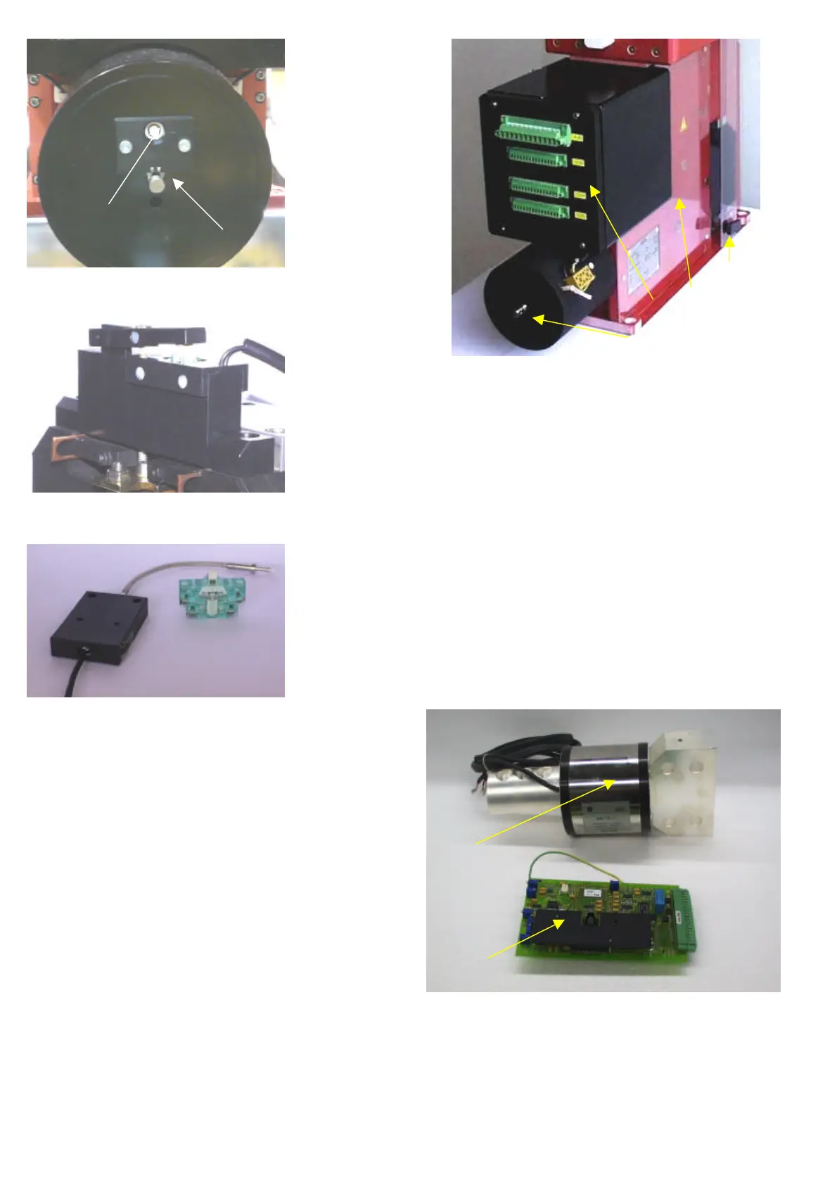
3.2.11 Solenoid closing drive (code nr: 3)
• For normal closing operations, the breaker is fitted with
a high power solenoid coil. The drive is mounted at the
front of the breaker and is equipped with a grounded
casing.
• Closing drive is supplied independently from other con-
trols (-X2 :1/:2), and directly from power source. Voltage
level shall be defined at the order. Rated power depends
of breaker type is between 1,8kW and 2,6kW.
• CLOSING command is enable by potential free contact
at (-X2 :4/:5) the signal durations shall be ~300ms.
• The closing drive system always includes a self-interrupt
control circuit (SU unit). This circuit enables a short acti-
vation with a time of ~150ms. SU unit switches power to
the solenoid and automatically switched it off after
~400ms.
• SU unit prevents also repeated drive activation (anti-
pumping), during continuous operation, due to an exist-
ing short circuit.
Fig. 16 Solenoid closing drive and control box
• In addition, the switch-in mechanism is electrically
blocked for approximately 8sec. or 14sec. after activa-
tion (see Table 2a “Activating magnet”). This prevents
premature activation following a short circuit.
3.2.12 Current measurement system (code nr: 6)
• The SEL current measurement system consists of the
sensing component (1) and signal-processing unit (2)
[Fig.17]. SEL sensor is integrated into a specially shaped
upper terminal of the breaker and is connected by a
shielded cable to the signal-processing unit. SEL control
unit is placed in the control-box [Fig. 18].
Fig. 17 SEL current measurement system
• SEL may be used for recording DC currents in selected
measurement ranges of 6kA or 12kA. Measurement of
rated current values and of the current rise may now be
made directly at the breaker.
Side protection
(2) SEL control
 Loading...


