S47183-e 01/2008 Design and specifications are subject to change without notice 37
6.1.1 General visual inspection
• Check out for damages or cracks of the frame, the
adapter or the arc chute.
• Check out the black marks on the countersunk screws.
These shall be joined together. If any screw is loosen-
ing, shall be replaced with new one, using glue, Loc-
tite222. Afterwards, mark the screw with black line to
sign its position in nest.
• Check out for missing screws or caps.
• Check out for deglutinated labels. Clean and fix it.
• Check out for corrosion. In case of finding significant
corrosion, please contact GE representative for con-
sulting.
• Check out for distinct manifestations of flame or
smoke at the frame. Especially in lower area of the
breaker. Please document it and contact GE represen-
tative for consulting.
• Clean the breaker from dirt and dust. Remove all dirt
with a dry clothes. No particularly high signs of abra-
sion (rough chips) should be seen anywhere.
• Clean and degrease the cooper terminals.
6.1.2 General functional inspection
Pay attention to the warnings, Section 1!
• In order to check the latch mechanism, the breaker
can be opened and closed with a hand lever.
Fig. 40 Using of the hand lever
• Switch remotely the breaker ON and OFF several
times using ST or UVR, and using closing drive. The
contacts must close after the CLOSE command and
must open following the OPEN command
• The breaker mechanism must not appear sluggish nor
must ON/OFF be unduly delayed.
6.1.3 Inspection of the arc chute
Pay attention to the warnings, Section 1!
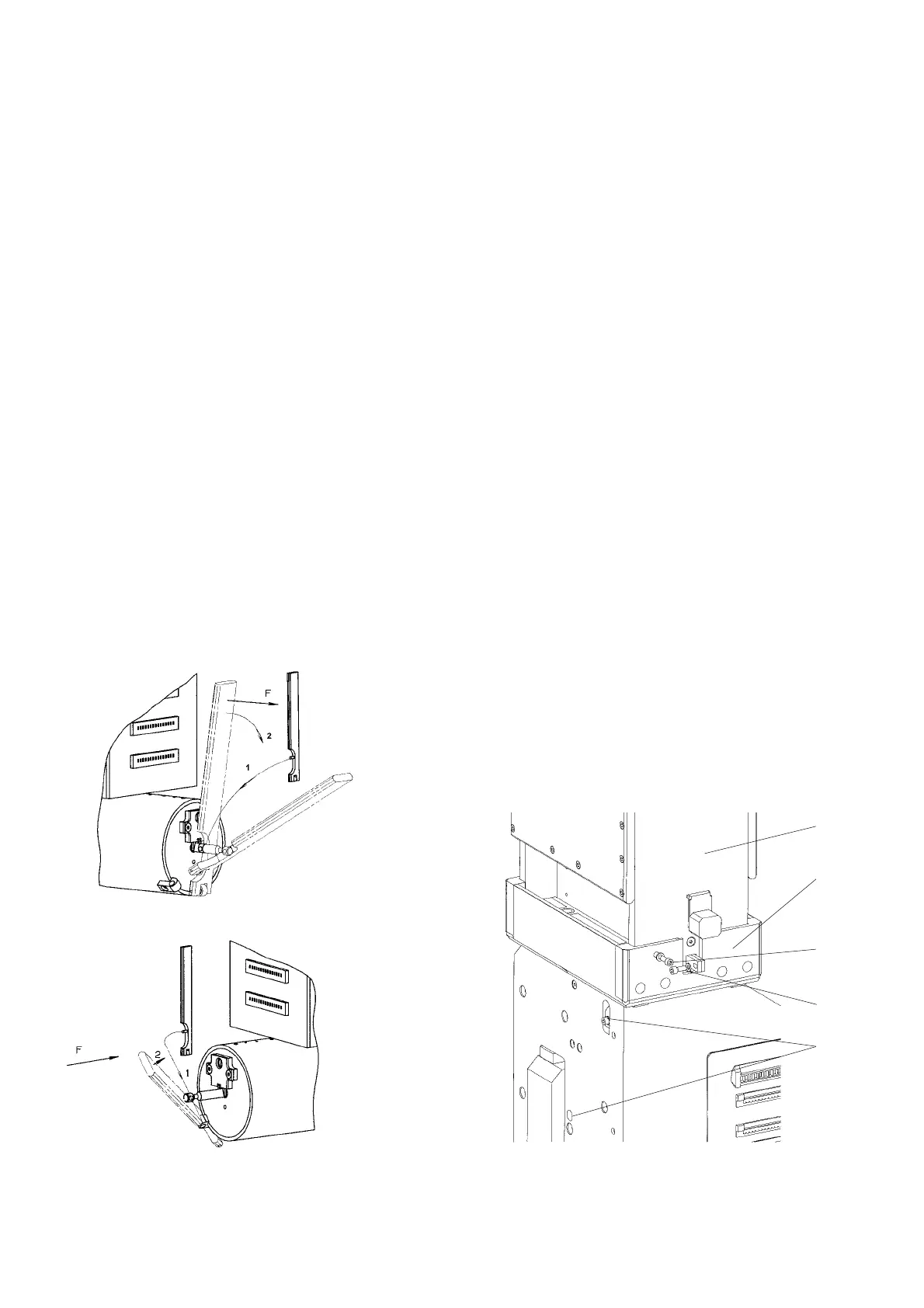
A) Remove the arc chute
• [Fig. 41]. Loosen the clamping screws (3) and (4), using
SW 5 hexagon wrench and take off the arch chute (1)
from the adapter (2).
B) Check the arc chute
• [Fig. 42]. Check the arc chute’s interior, as far as pos-
sible, for deposits (1). There shall not be copper pearls
on the metal-plates, which could partially link the
plates.
• [Fig. 42]. Check the general condition of the insulation
plates (4). These shall no be bended or burned. Also
other insulation shall not be heavily damaged.
• [Fig. 42]. Check the arc horns (2). Its cross section shall
not be reduced more than ~30%.
• [Fig. 42] Check the splitting plates (3). These shall not
be burned more than ~20mm [~0,8in].
C) Install the arc chute
• [Fig. 41]. Put in arc chute (1) into adapter (2).
• [Fig. 41]. Tighten front- and backside connections of
the arc runners (3), including lock washer. Use a
torque of 10 Nm [88 lbf*in].
• [Fig. 41]. Tighten front- and backside of the arc chute
connections (4), including flat washers. Use a torque of
5 Nm [44 lbf*in].
Fig. 41 Arc chute and arc runners fixing
3
1
2
4
5
 Loading...


