S47183-e 01/2008 Design and specifications are subject to change without notice 39
6.1.5 Inspection of contacts’ tilt and gap
Pay attention to the warnings, Section 1!
A) Remove the arc chute and adapter
• See 6.1.4-A/B.
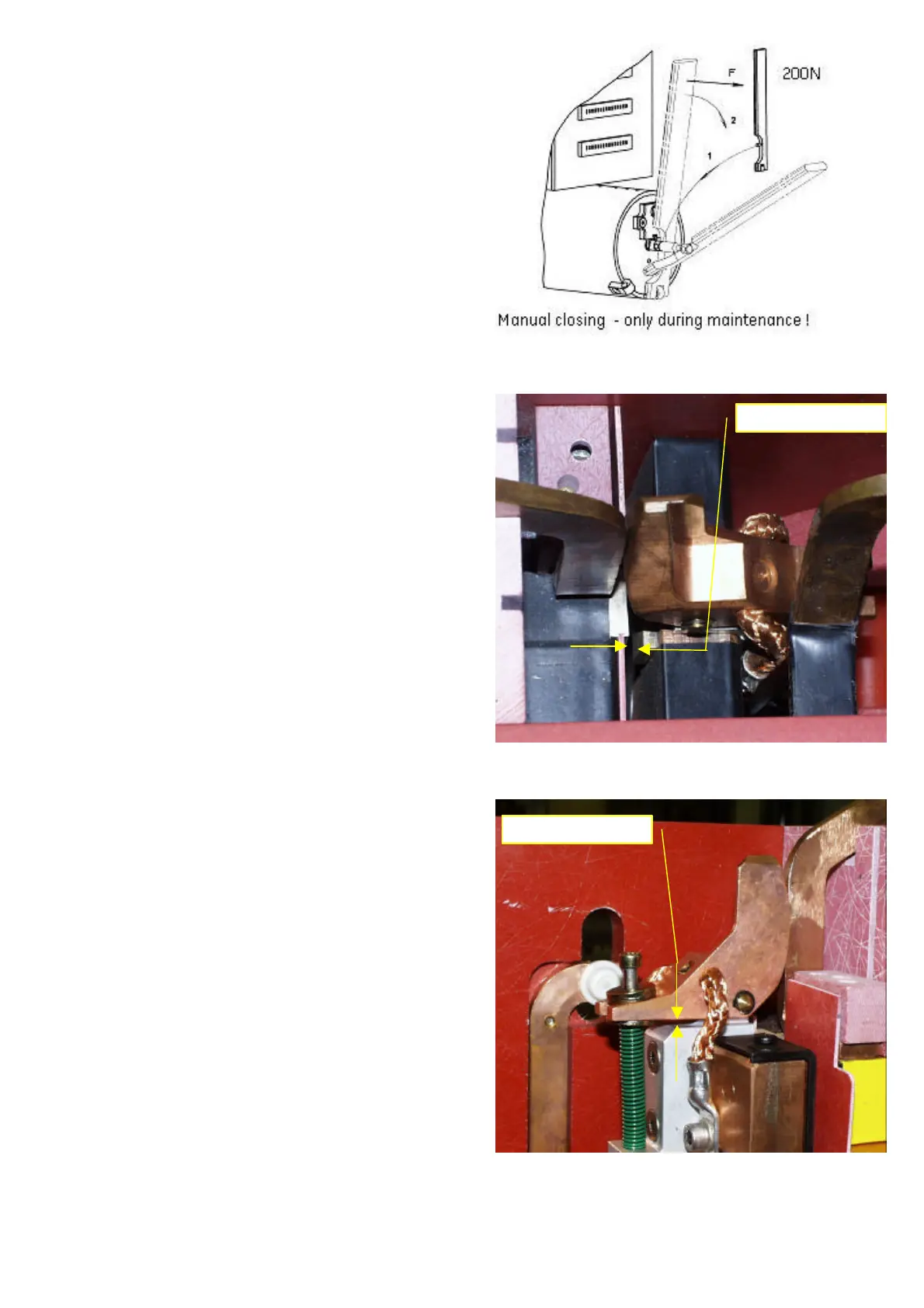
B) Check the tilt of the main contacts
• [Fig. 45]. Use the hand lever for slowly closing the
main contacts.
• [Fig. 46]. Once the pre-arcing contact touches arc
runner, check the air gap between main contacts. The
gap between main contacts shall have more 1mm
[0,04in].
• In case of insufficient tilt, replace the pre-arcing con-
tact with new one. See 6.2.1 and 6.2.2 for details.
• If required tilt is not available, even after component
replacing, please contact GE Service Team.
C) Check the air gap of pre-arcing contact
• Close the breaker and secure the solenoid drive
against unintended opening. See 1.2.1.
• [Fig. 47]. Check the air gap between the pre-arcing
contact and main arm. It shall be minimum 1mm
[0,04in].
• In case of insufficient tilt, replace the pre-arcing con-
tact with new one. See 6.2.1 and 6.2.2 for details.
• If required gap is not available, even after contact re-
placing, please contact GE Service Team.
D) Install back adapter and arc chute
• See 6.1.4-G/H.
6.1.6 Inspection of the screw connections
Pay attention to the warnings, Section 1!
• [Fig. 41]. Tighten front- and backside of the arc runner
screw connections (3) and (5). Use torque of 10Nm
[88lbf*in].
• [Fig. 41]. Tighten arc chute connections (4). Use torque
of 5Nm [44lbf*in].
• [Fig. 41]. The arc runner’s screw connections (3) must
be secured by means of lock washer.
• [Fig. 41]. The arc chute’s screw connections (4) must
be secured by means of flat washer.
• Any other screws shall be tightening with applied
torques from Table 3-D.
• Ensure that the screws are in good condition, that
thread and nest are not damaged. Surface shall be
free from rust. Replaced any screw, which does not
fulfil above conditions.
• This check must be carried out prior to commissioning
and after every maintenance.
6.1.7 Inspection of the mechanic components
Only GE Service Team or its representative shall do these
inspections. These are related with major disassembling
and adjusting of the breaker. Customer without supervi-
sion of trained specialist shall not execute these.
Fig. 45 Closing operation by using hand lever
Fig. 46 Inspection of the main contacts’ tilt
Fig. 47 Inspection of the pre-contact’s air gap
 Loading...


