8 Design and specifications are subject to change without notice S47183-e 01/2008
3.2.5 Electro-Dynamic tripping device (code nr: 12)
• ED tripping device requires an external protective re-
lay/system for monitoring a current increase. This re-
lay/system belongs to customer’s installation.
• If a fault occurs, an external relay, releases signal into
the capacitors’ control unit (internal NEKO or external),
which discharges abruptly its energy into ED coil [Fig. 8].
The coil trips the breaker’s quick latch and cause open-
ing within time of less 3ms.
• ED tripping device is offered as an option. Standard set
consist of ED coil and electronic control unit with C-bank
installed in (NEKO). The external release signal shall have
6V to 24V DC, and shall be fed at (-X2 :10 / :11).
• Customer may use it’s own C-bank unit. Rated voltage of
300VDC and capacity of 2000uF is required. In this case
only ED coil will be installed into the breaker.
• Be sure, that voltage level is between 6V…24V and
there are no spikes on signal with duration <3msec.
This can lead to major defect of the NEKO board!
• Maximum duration of the firing signal must not ex-
ceed ~1sec. Longer signal will lead to NEKO failure! It
is highly recommended to use an internal auxiliary con-
tact in serial connection with firing circuit (-X2 :10/:11). It
will automatically cut off the firing circuit after contacts
are opened.
Fig. 8 ED tripping coil with seesaw interface
3.2.6 Auxiliary tripping devices (code nr: 11).
• The breaker can be equipped with either a shunt trip (ST)
or a zero voltage release (UVR). It is not possible to have
both devices installed in the same breaker.
• In standard configuration, internal voltage converter
(code nr: 8), supply the devices with 24VDC. This con-
verter transforms any externally connected voltage, into
internal 24VDC, required by breaker’s controls.
• Optionally, it’s possible to supply both devices with direct
external 24VDC ± 5%. In this case release signal for ST
shall not be longer 100ms.
• Both devices are tripped by potential free contact con-
nected accordingly.
• Both devices are interchangeable.
• The ST is used for remote actuation. It is designed for
short time operation with maximum duty cycle of 9%.
ST’s supply is connected through the auxiliary contact,
which cut off supply voltage after breaker’s opening.
This protects ST against overheating.
• The UVR [Fig. 9] is used for remote actuation and, in
combination with an internal electronic control, for volt-
age control.
• The UVR releases at voltage interruption or voltage loss
>3V. In these cases UVR trips the breaker. It is therefore
possible to use this device in combination with the elec-
tronic trip unit for voltage monitoring, i.e. for motor
switches, where an unintended re-start of machines af-
ter a temporary voltage breakdown is to be prevented.
• The UVR is intended for continuous operation. Its rated
power is 40W.
• Due to their operational mode, UVR is self-monitoring
device, i.e. when the breaker is tripped upon a break of
the pilot wire (EMERGENCY-OFF principle).
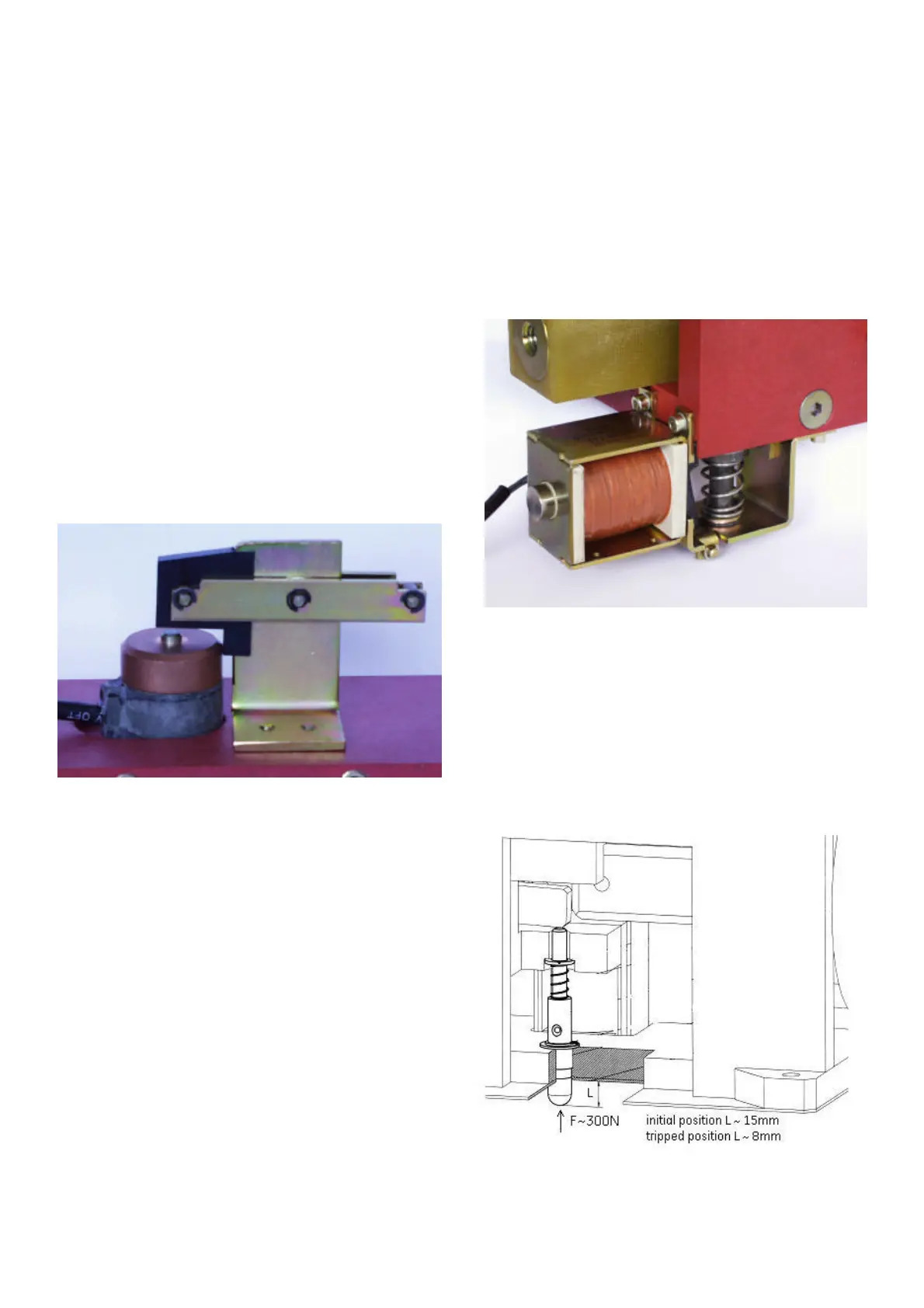
Fig. 9 Zero voltage release
3.2.7 Forced tripping release (code nr: 13)
• Optionally, the forced tripping release (FTU) can be in-
stalled in the breaker [Fig. 10a]. This unit is used for me-
chanical tripping of the breaker, by means of pressing
the pin at the bottom plate. Force required to trip the
breaker is about 300N (~67,5 lbf).
• The tripping pin position is as on Fig. 10b.
Fig. 10a Forced tripping release
(~0,6 in)
(~0,3 in)
 Loading...


