42 Design and specifications are subject to change without notice 01/2008
6.2.2. Maintenance of contact system (before 11/2003)
Pay attention to the warnings, Section 1!
This section is valid for breakers manufactured before
11/2003.
This section refers to maintenance works A, B, C from Ta-
ble 4.
A) Remove the arc chute and adapter
• See 6.2.1-A/B.
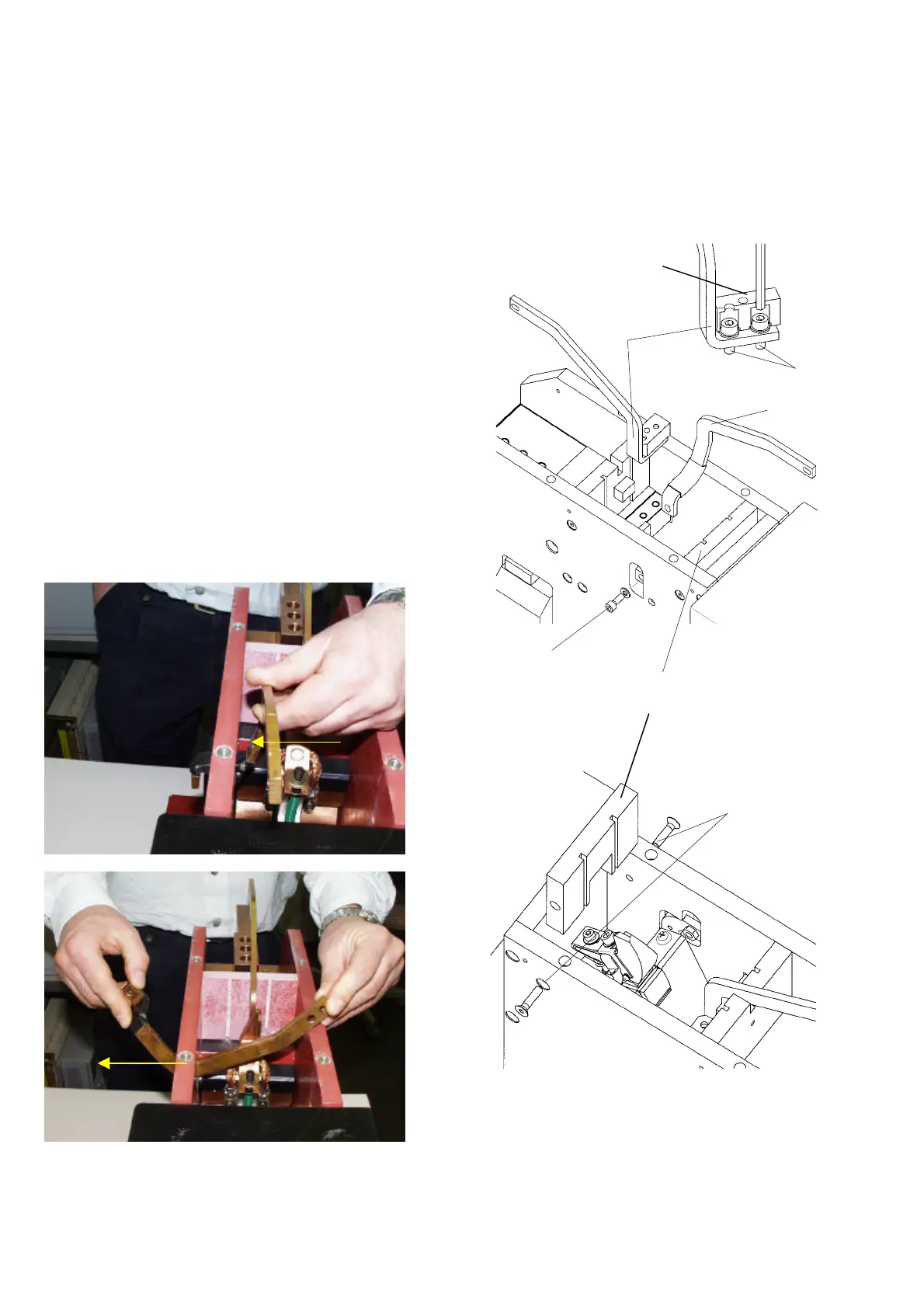
C) Changing the protective walls and arc runners
• [Fig. 48]. Pull out two protective walls (3).
• [Fig. 51-2]. Loosen screws (6a) with tool (SW4) and take
out front wall (6).
• [Fig. 51-2]. Loosen screw (5a) with tool (SW5).
• [Fig. 51-1]. Take out the front arc runner as it’s shown.
• [Fig. 51-2]. Take out the back arc runner (4) by loosen
two screws (4a) with tool (SW5). Don’t remove the pro-
tective cap (4b).
• [Fig. 51-2]. Install new front-arc runner (5) and new
back-arc runner (4). Tighten it using torque of 10Nm
[88lbf*in].
• [Fig. 51-2]. Install front wall (6) and adjust it by posi-
tioning the protective wall (3) [Fig. 48]. Tighten it using
torque of 10Nm [88lbf*in]
• [Fig. 48]. Put in two new protective walls (3).
Fig. 51-1 Taking out the front arc runner of old design
Fig. 51-2 Changing pre-arcing contact
6a
5a
5
4a
6
4
4b
 Loading...


