22 Design and specifications are subject to change without notice 01/2008
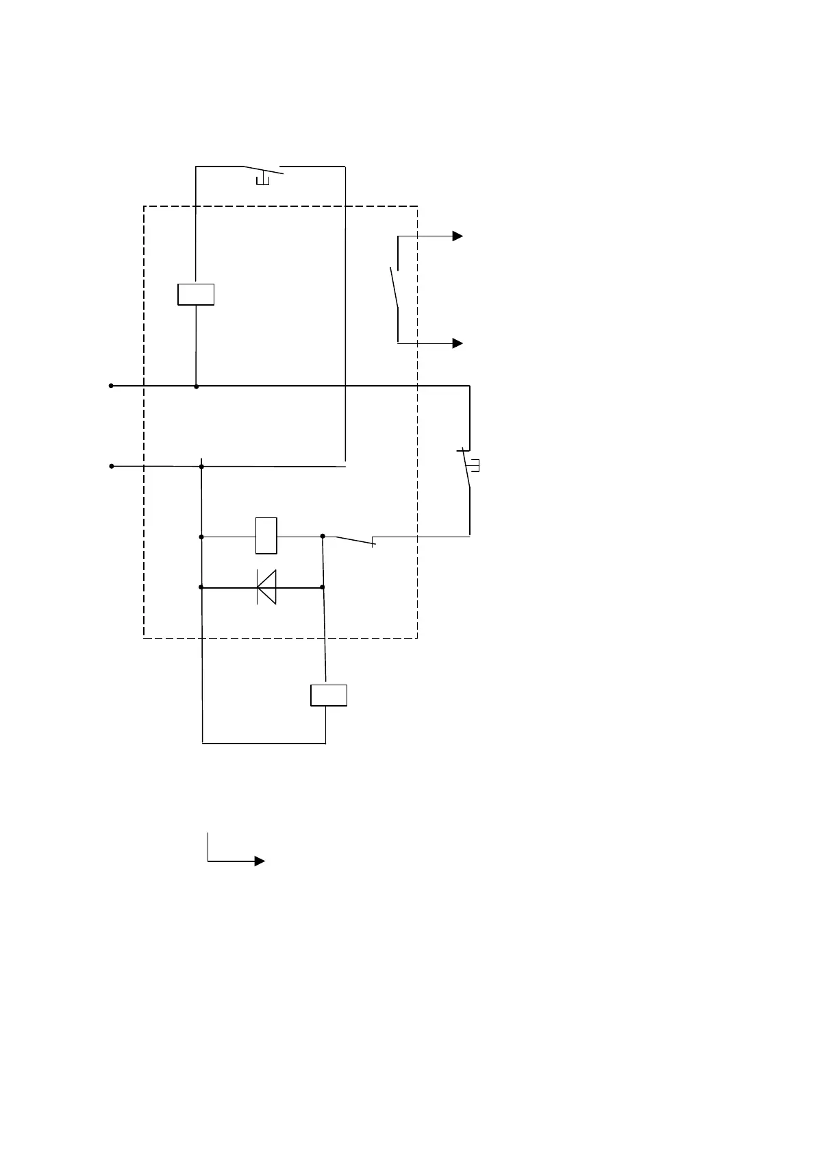
4.3.7 Zero voltage release control unit
• The EM-STOP signal is provided for resetting K2 on the SU-control circuit. It effects with priority in switching OFF (by ST or
UVR) before switching ON. Once switching ON and OFF signals are simultaneous, switching OFF command will stay
longer than switching ON. It means, that OFF command is master command.
• -S2 (-X2 :6/:7) is NO contact, predicted for indirect releasing of the UVR by relay -K2
• -S2 (-X2 :8/:9) is NC contact predicted for direct releasing of the UVR. If it’s not used, please short this connection perma-
nently.
Fig. 28 UVR control circuit
U<
3
4
5
6
:7
:6
2
1
7
8
9
10
-S2
-X2
-X2
- X13
-K2
-K1
-K1 -K2
-D1
-X2
-X2
-S2
24 V
-
+
A1
A2
A1
A2
Key position - 5
Key number – 00: Without shunt trip or zero voltage release.
20: With zero voltage release.
Emergency STOP
signal
Emergency STOP
signal
 Loading...


