S47183-e 01/2008 Design and specifications are subject to change without notice 45
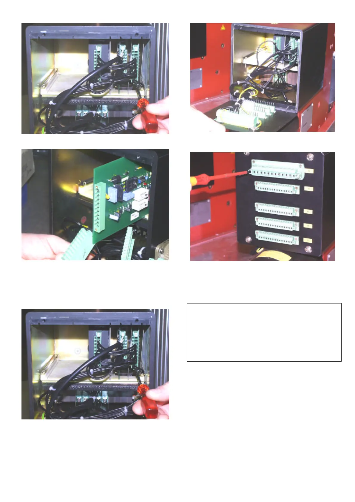
Fig. 55-4 Unscrew all the plugs from control boards
Fig. 55-5 Pull out the plugs of the control boards. Pull
out selected control board. Insert new control board
• Listen that both, the isolation plate at the side of
equipment and the isolation plate at the side of sol-
dering, were inserted!
Fig. 55-6 Plug in all control plugs and tighten it by the
bolts
Fig. 55-7 Pay attention, that no cables will be crisped
between box and front cover during closing!
Fig. 55-8 Carefully close the control box with the front
cover, and fix the four screws
• Put on plugs X2…X6, fix the screws of the plugs and
switch on control voltage.
Checking the breaker:
• Make 3 times ON /OFF switching in the „Test-position“
of the draw out version/the installation. The breaker
has to switch ON/OFF without any time lag.
• If the test succeeds, reconnect the breaker to the
main circuit.
 Loading...


