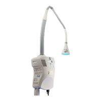
Component Description
User
interface
indicators
Colored indicators on the front face of the system provide information as to the
device status. The standby/on indicator is illuminated in green whenever AC Power
is applied and the system is in standby mode indicating there are no alarms/faults
and the system is ready to operate. When the standby/on switch is briey depressed
to activate the system and turn light on, the standby/on indicator turns blue and the
over-temperature/under-temperature red indicator briey illuminates to indicate
that it functions. Turning o the light is controlled in the same fashion by pressing
the standby/on switch to put the system in standby mode. The standby/on indicator
turns green. The over-temperature/under-temperature indicator provides alarm
indications for both internal over-temperature and under-temperature conditions.
The temperature limits are factory set and non-adjustable. If the temperature
limits are reached, the therapeutic-light LED is automatically turned o but the
internal fan continues to operate during the fault conditions in order to bring the
internal temperatures back to normal operating conditions. Once the temperature
is within the normal range, the fan turns o and the standby/on indicator turns
green signifying that the device is ready for operation. The over-temperature/under-
temperature indicator is on continuously during under-temperature conditions and
ashes repeatedly during over-temperature conditions.
Power supply
board
The system includes a universal switching power supply board that can accept
AC input voltages in the range of 90-264 VAC at frequency range of 47-63 Hz to
generate 12 VDC output that feeds the LED driver board.
Power input
connection
and fuses
The power cord connects to the input power connector located on the bottom of the
device. This input power connector provides EMI protection and also houses two AC
line fuses (T3.15A @ 250V~, slo-blo type) which are accessible from the outside of the
system unit.
2. Light pipe: The light pipe provides a stable self-supporting, adjustable arm that allows easy, low-force
positioning of the light onto the patient. It also allows for easy unobstructed access for the operator
to the patient. The light pipe contains optical components; therefore it should be treated with extreme
care as damaging these components can severely diminish the light output. The light pipe contains
an internal ber that is used to transmit the light generated by the light box out to the light shade. The
light shade includes an output reector which serves to uniformly project the light over a desired area.
The shade also includes a protective cover which serves to enclose the output reector, protecting it
from dust and debris while simultaneously protecting users from touching the ber end. If needed, the
protective cover can be cleaned gently using an optical cleaner and a lint-free wipe.
46
Chapter 6: System Description

 Loading...