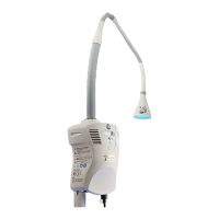
1.3 Controls, Indicators, and Connections
Figure 1-1
1. Light shade
2. Light pipe
3. Hour meter display
4. Exhaust vents
5. Over/under temperature indicator
6. Standby/on indicator
7. Standby/on switch*
8. Light box
9. Power cord inlet*
10. Fuses Compartment
11. Intake vents/air lter
12. Potential equalization stud
13. Light pipe port
14. Light shade protective cover
* To isolate the device from the supply mains:
• For a wall-connected device, unplug the power cord.
• For a device connected to a microenvironment’s accessory outlet, switch o the mains switch on the back of the
microenvironment.
1
2
3
4
5
6
7
FRONT BACK
BOTTOM
8
13
14
12
11 9
10
14
Chapter 1: Product Overview

 Loading...