22
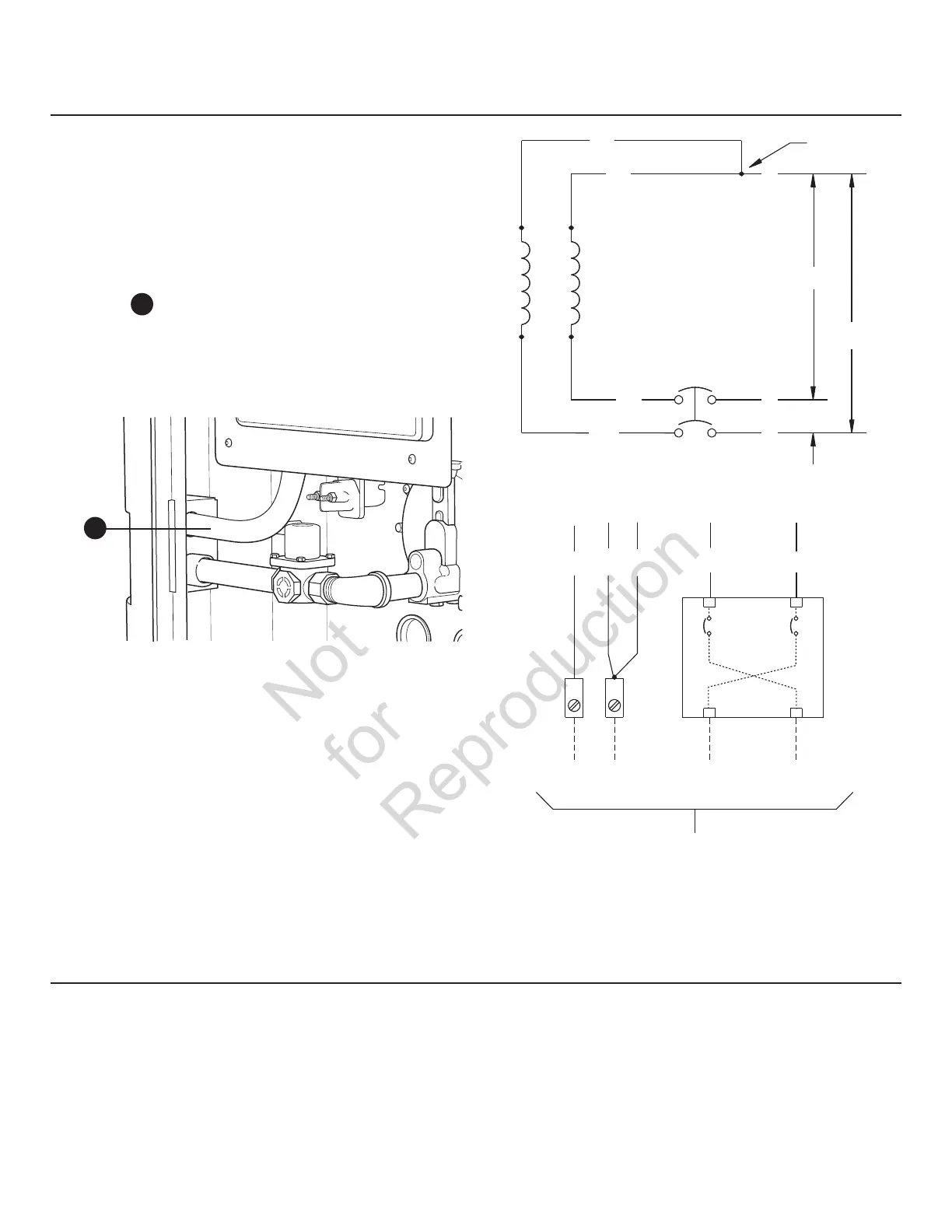
Generator AC Connection System
A single-phase, three-wire AC connection system is used in
the home generator. The stator assembly consists of a pair
of stationary windings with two leads brought out of each
winding. The junction of leads 22 and 33 forms the neutral
lead, as shown schematically and as a wiring diagram. A
complete schematic and wiring diagram can be found later
in this manual.
NOTICE
Neutral is not bonded to ground at generator.
The conduit
A
between the corner electrical inlet and the
control panel is a UL requirement. If removed, it must be
replaced with similar conduit.
33
240V
11
22
44
120V
120V
1122 33 440
Neutral
Power Winding
Circuit
Breaker
Line 1
Neutral
To Transfer Switch
Line 2Ground
Circuit
Breaker
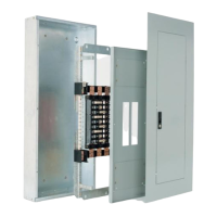
Ground the home generator per applicable codes, standards,
and regulations. The generator GND lug is located inside the
control panel box.
Grounding the Generator
A
 Loading...