23
Utility Circuit Connection
“240V Utility” leads must be routed in conduit. The “240V
Utility” leads deliver power to the generator’s circuit board,
optional battery warmer and optional oil warmer. This power
also charges the battery. When power on these leads is lost,
the generator will start.
Using provided 2 pin connector plug and installer-supplied
minimum 300V, 14 AWG copper wire, connect each control
circuit terminal in the generator to the two-amp fuse
terminals in the automatic transfer switch.
When making connections, obey wire type and torque
specifications printed on the circuit breaker and neutral/
ground connector.
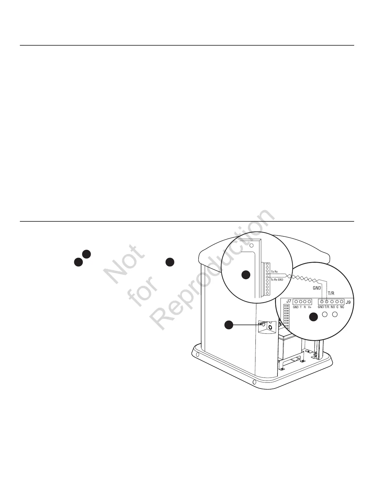
Transfer Switch Communication
(Units with ACCM II or later transfer switch only)
Using #18 AWG twisted pair conductors, no greater than
200 ft in length, connect Tx Rx and Tx Rx GND from the
generator control panel
A
to T/R and GND on the transfer
switch control board
B
via the low voltage access hole
C
.
B
A
C
 Loading...