25
If mandated by local code, construct a concrete slab at least
3 in (76 mm) thick and 6 in (152 mm) longer and wider than
the unit (34.6 in (880 mm) x 39.4 in (1000 mm)). Attach unit to
slab with 1/4” (6 mm) diameter (minimum) masonry anchor
bolts long enough to retain the unit.
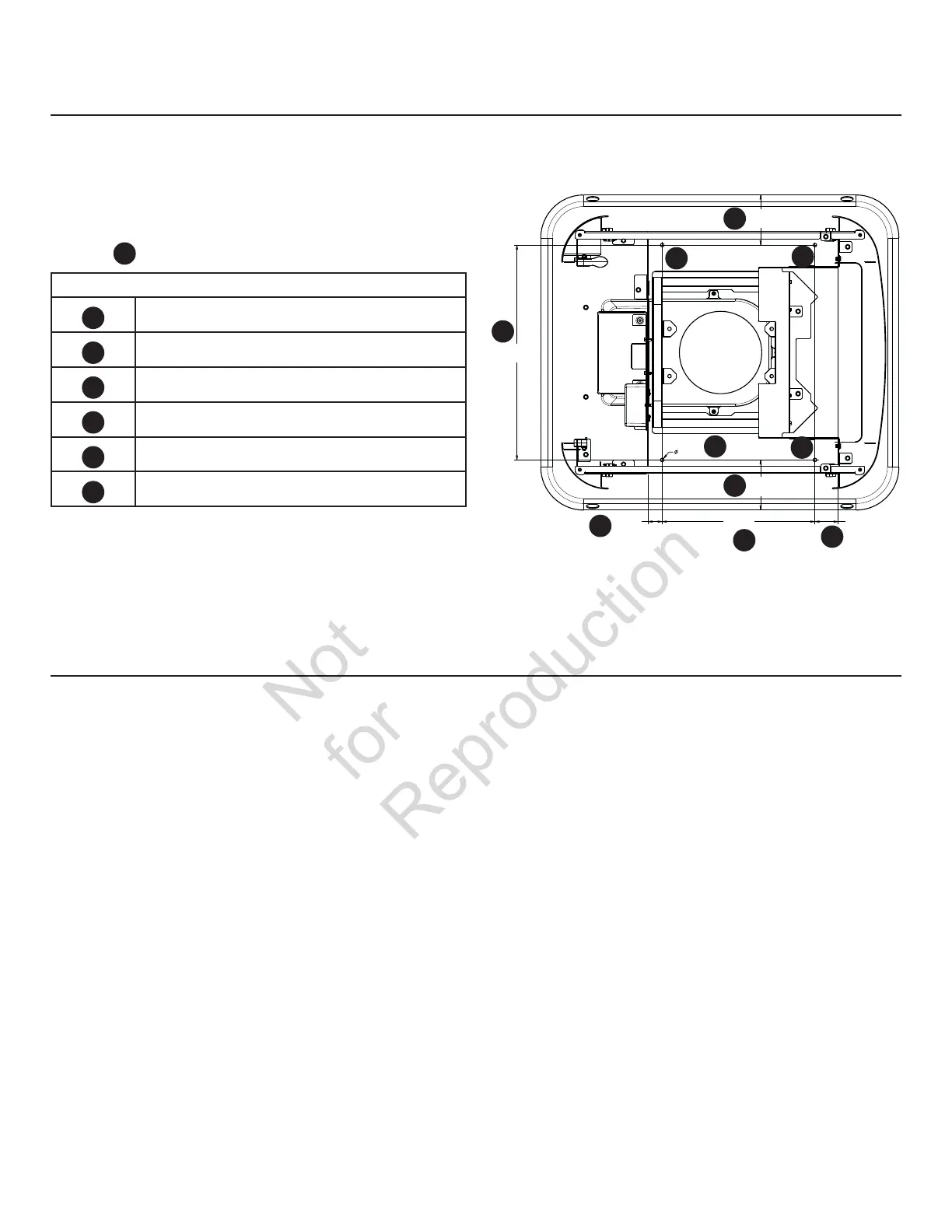
Drill anchor bolt holes into the unit base at the four ideal
locations
F
indicated.
Anchor Bolt Drill Location Measurements
A
5.51 in (140 mm)
B
23.62 in (600 mm)
C
16.78 in (426.4 mm)
D
2.55 in (65 mm)
E
1.57 in (40 mm)
F
1/4 in (6 mm) holes
140
40
140
426.4
23.62 in
(600mm)
5.51 in
(140mm)
1/4 in
(6mm)
1.57 in
(40mm)
5.51 in
(140mm)
16.78 in
(426.4mm)
2.55 in
(65mm)
A
D
B
E
C
F
F
F
F
Concrete Slab (Optional)
A
Gravel Base (Optional)
If mandated by local code, clear an area approximately five
inches deep and about six inches wider that the foot print
of the standby generator. Line the area with polyurethane
film and fill with pea gravel or crushed stone. Compact and
level the stone. If concrete slab is required, see Concrete Slab
section in this manual.
 Loading...