– 26 –
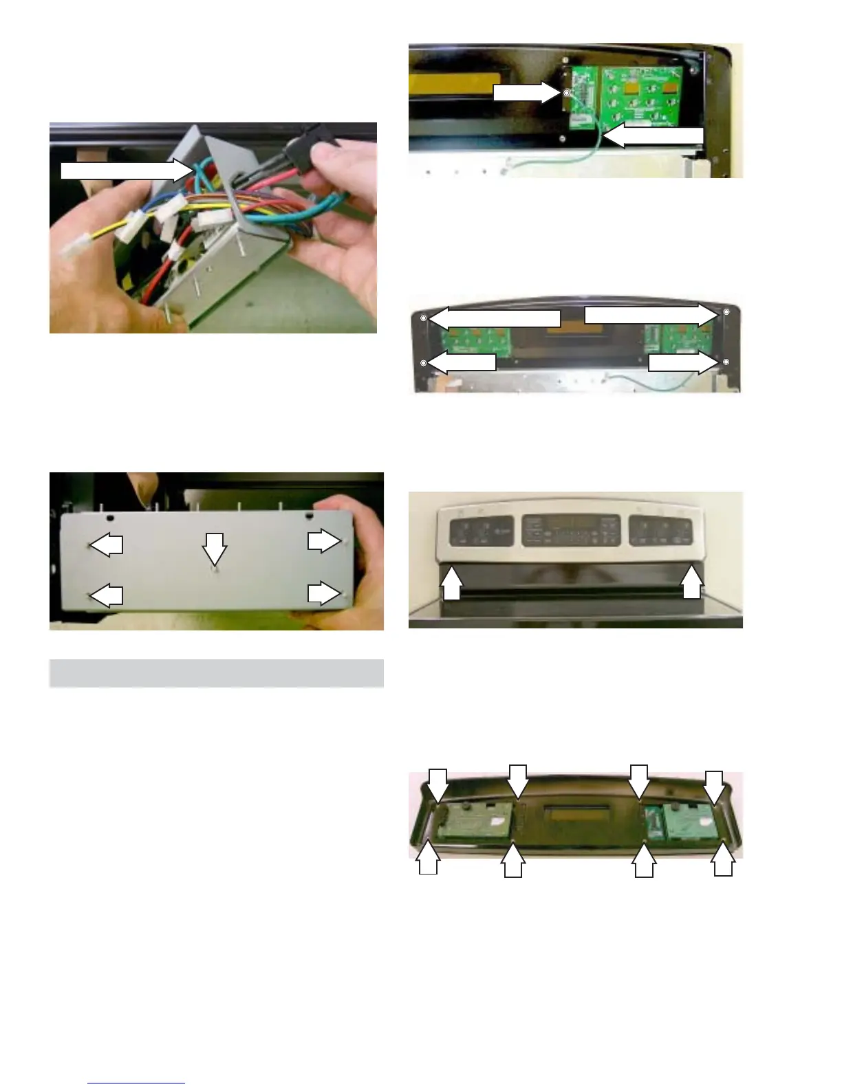
10. Remove the control panel from the oven.
11. Remove the 8 screws and touch panel from
the control panel.
7. Remove the 2 screws and 2 washers from
the rear of the control panel.
8. Remove the 2 screws from the oven.
9. Remove the 2 screws from the front of the
control panel.
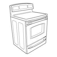
10. Remove the electrical connector, wire bundle,
and 2 grounding wires from the circuit board
mounting box.
11. Release the five mounting clasps that hold the
cooktop power circuit board to the circuit
board mounting box. Remove the cooktop
power circuit board and retain the circuit board
mounting box.
2 Grounding Wires
Screw
Ground Wire
Control Panel Assembly - JB988
The control panel assembly contains the ERC,
infinite heat switches (on models JB905 and
JB968), Electronic Burner Controls (on model
JB988), and Touch Sensor Board.
Removal and Replacement
1. Disconnect power.
2. Remove the back cover.
3. Remove the
Left Side EBC - JB988.
4. Remove the
Oven ERC.
5. Remove the
Right Side EBC - JB988.
6. Remove the screw and disconnect the ground
wire.
Screw
Screw
Screw and Washer
Screw and Washer
 Loading...