– 33 –
Note: Jumpers that are hard-wired to the circuit
board are not listed.
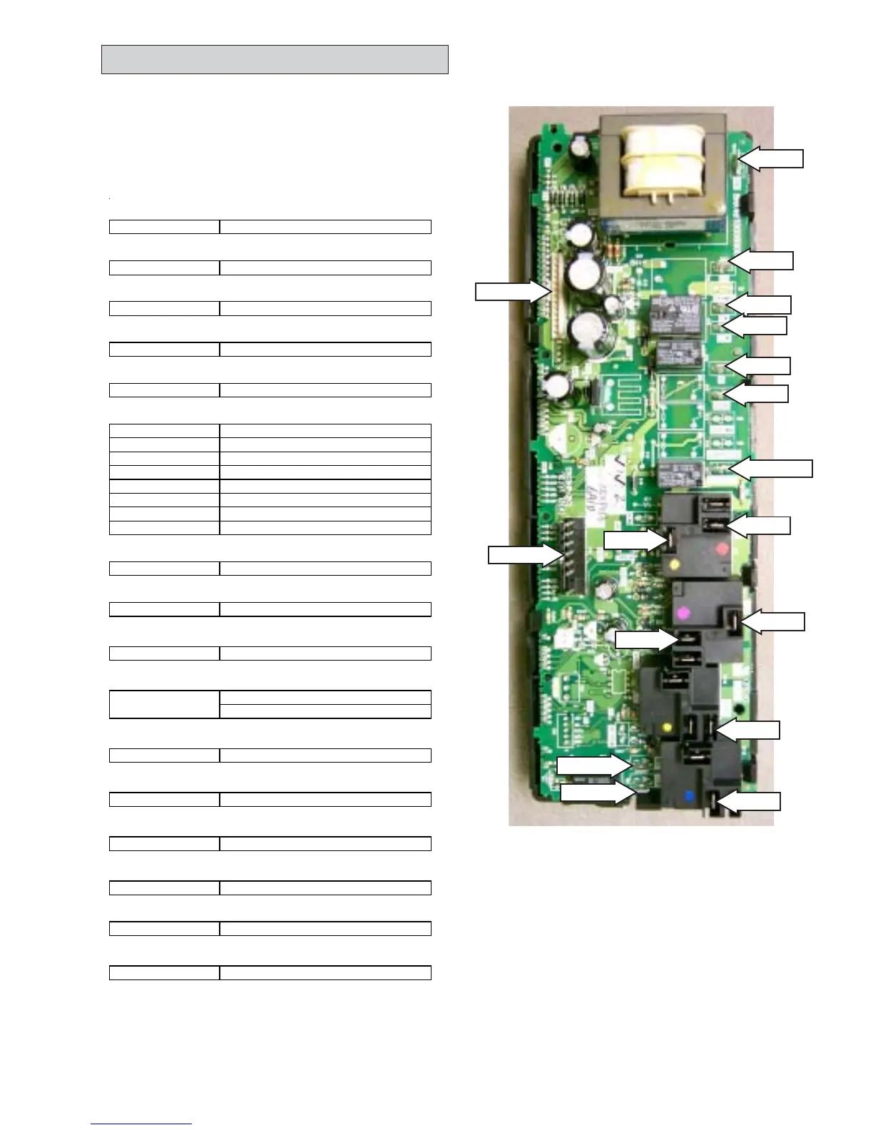
ERC Circuit Board
The ERC Circuit Board contains the relays,
terminals, and other components needed to
perform the proper switching and control of oven
functions. A list of ERC circuit board connections
is provided below:
BAKE (BA on Wiring Diagram)
Y-1 Bake Element
BROIL (BR on Wiring Diagram)
V-1 Broil Element
CW
RW-1 Fan Motor
CCW
N-2 Fan Motor
CN1
Pin 1 to Pin 14 Oven Touch Pad
CN2
Pin 1 C-2 Meat Probe Jack
Pin 2 C-1 Meat Probe Jack
Pin 3 Y-1 Lock Motor Switch
Pin 4 N-3 Lock Motor Switch
Pin 5 O-7 Lock Motor Switch
Pin 6 W-6 Oven Temp Sensor
Pin 7 - Not Used
Pin 8 W-5 Oven Temp Sensor
COM
B-7 Input - Common
CONV
N-4 Convection Heating Element
COOK
W-4 Left Touch Pad
DLB
Bake Element - Common
O-1
Broil Element - Common
GND
GN-2 Ground
L1
B-7 Input - Common
L1A
O-1 Input - Common
L2
R-4 220 Volt - Input
N
W-4 220 Volt - Input
OV-LIGHT (LIGHT on Wiring Diagram)
R-4 220 Volt - Input
GND
L1
CW
CCW
N
Cook
L2
L1A
Bake
OV-Light
CN1
Broil
MDL
COM
CN2
CONV
DLB
 Loading...