GE HEALTHCARE
DIRECTION 5162630, REVISION 3 LOGIQ™ S6 SERVICE MANUAL
Section 3-5 - Installation Paperwork 3-19
3-5-1-1 Rear Panel Connector (cont’d)
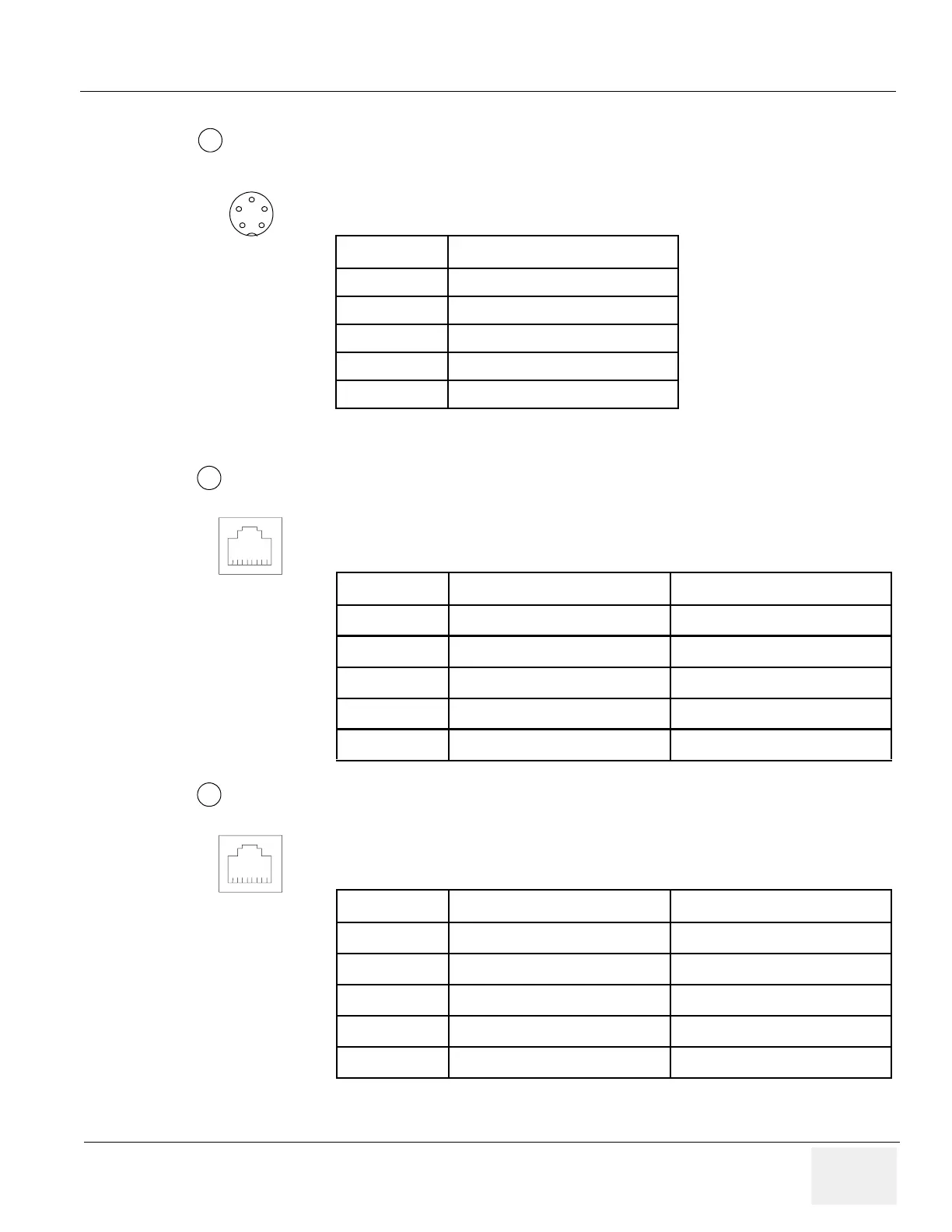
Pin Assignment of Foot Switch
Round 5 pin connector.
NOTE: Output level of control signals indicated in the above tables are TTL level.
Pin Assignment of Ethernet
Connector: RJ-45 Modular, 8-pin
Pin Assignment of Insite
Connector: RJ-11 Modular, 6-pin
Table 3-26 Pin Assignment of Mini-Jack for Footswitch
Pin No Output Signal
1SW1-WH
2SW2-RD
3SW3-GN
4 SW1-BK, SW2-BK, SW3-BK
5Frame GND
Table 3-27 Pin Assignment of Ethernet Connector
Pin No Output Signal Description
1 ETHER TD Ethernet TD+
2 ETHER TD Ethernet TD-
3 ETHER RD Ethernet RD+
6 ETHER RD Ethernet RD-
Others NC Non-connection
Table 3-28 Pin Assignment of Insite Connector
Pin No Output Signal Description
2 TEL L4 Telephone L4
3 TEL L2 Telephone L2
4 TEL L1 Telephone L1
5 TEL L3 Telephone L3
Others NC Non-connection
4
1
2
3
4
5
5
8 1
6
8 1
 Loading...


