GE HEALTHCARE
DIRECTION 5162630, REVISION 3 LOGIQ™ S6 SERVICE MANUAL
3-20 Section 3-5 - Installation Paperwork
3-5-1-1 Rear Panel Connector (cont’d)
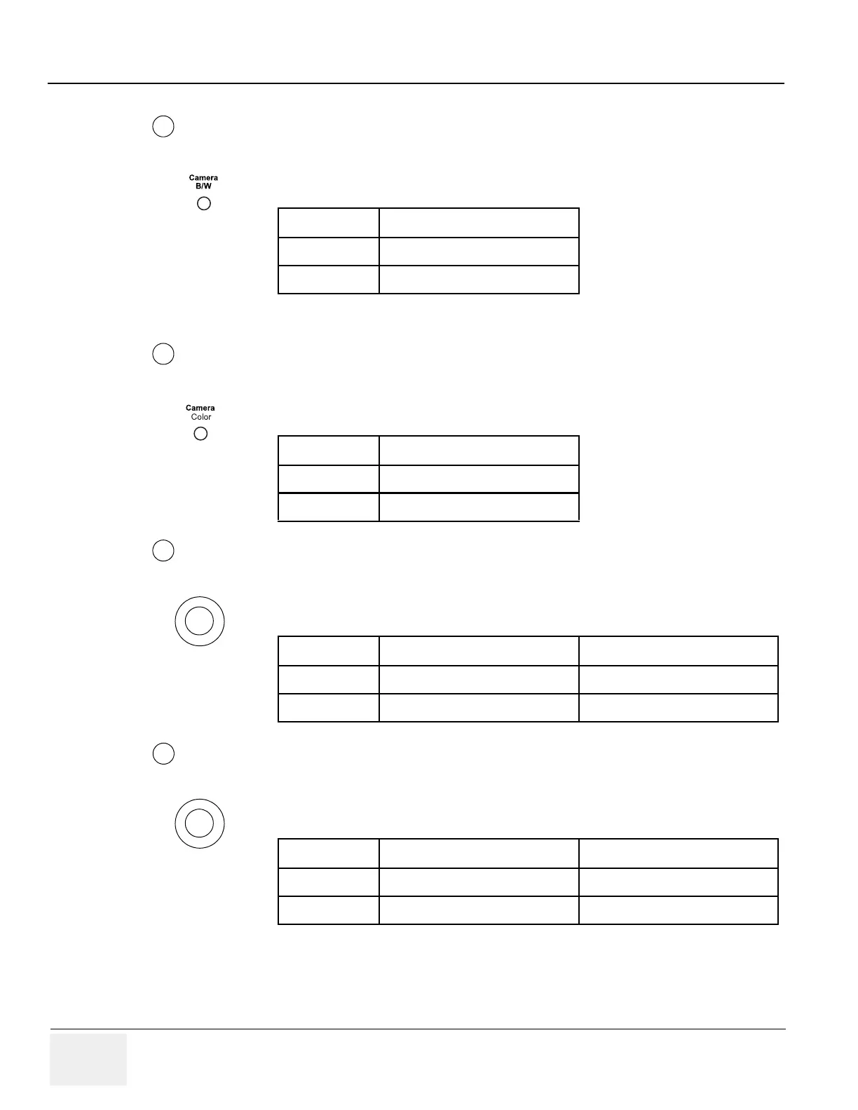
Pin Assignment for Camera B/W
NOTE: Output level of control signals indicated in the above tables are TTL level.
Pin Assignment of Insite
Pin Assignment of Audio
RCA pin Jack
Pin Assignment of Composite Out, B/W
BNC Connector
Table 3-29 Pin Assignment of Mini-Jack for Controlling B/W Camera
Pin No Output Signal
1PRINT
2 Signal GND
Table 3-30 Pin Assignment of Mini-Jack for Controlling Color Camera
Pin No Output Signal
1SHUTTER
2 Signal GND
Table 3-31 Pin Assignment of RCA pin Jack
Pin No Output Signal Description
1 Audio OUT/IN Signal
2 Audio OUT/IN GND
Table 3-32 Pin Assignment of BNC Connector
Pin No Output Signal Description
1 Composite Video B/W
2 Composite Video GND
7
8
9
10
 Loading...


