CHAPTER B: DC POWER INPUT DC POWER INPUT
MULTILINK ML1200 MANAGED FIELD SWITCH – INSTRUCTION MANUAL B–3
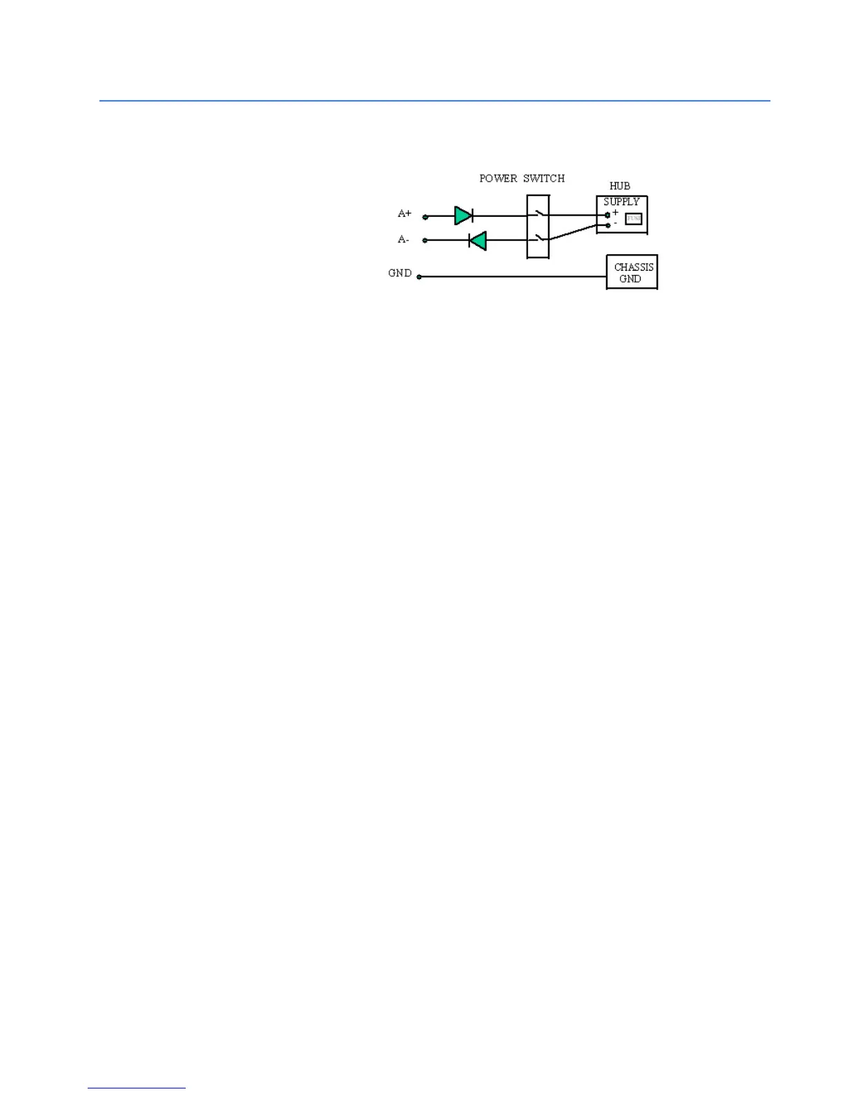
B.2 -48 V DC, 24 V DC and 125 V DC Power, Theory of Operation
The -48VDC, 24VDC and 125VDC power options are designed using diodes inside on each
DC power input line behind the two external power connection terminals, so that the
power from an external source can only flow into the hub. This allows the Switch to
operate only whenever DC power is correctly applied to the two inputs. It protects the
Switch from incorrect DC input connections. An incorrect polarity connection, for example,
will neither affect the Switch, its internal power supply, nor will it blow the fuse in the
internal power supply.