CHAPTER 3: INSTALLATION INSTALLATION
MULTILINK ML1200 MANAGED FIELD SWITCH – INSTRUCTION MANUAL 3–7
For best cooling of the ML1200, attach the metal brackets to metal (rather than wood or
plastic). Attaching to metal helps conduct heat away from the ML1200 through the metal
brackets and into the metal support structure.
Since the ML1200 has special internal thermal techniques (patent pending) to move the
heat generated by the electronic components inside into the case, the case may be quite
warm to the touch during normal operation.
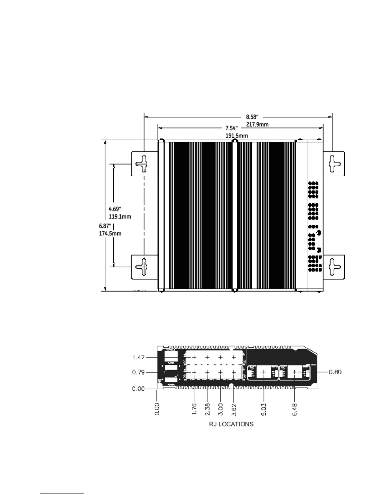
The unit is mounted using the brackets as shown in the illustration above. The spacing for
the mounting screws into the supporting wall or panel is a rectangle 21.74 x 11.91 cm (8.56
x 4.69 inches) center-to-center.