SecoGear 24kV-27kV Air Insulation Switchgear
12
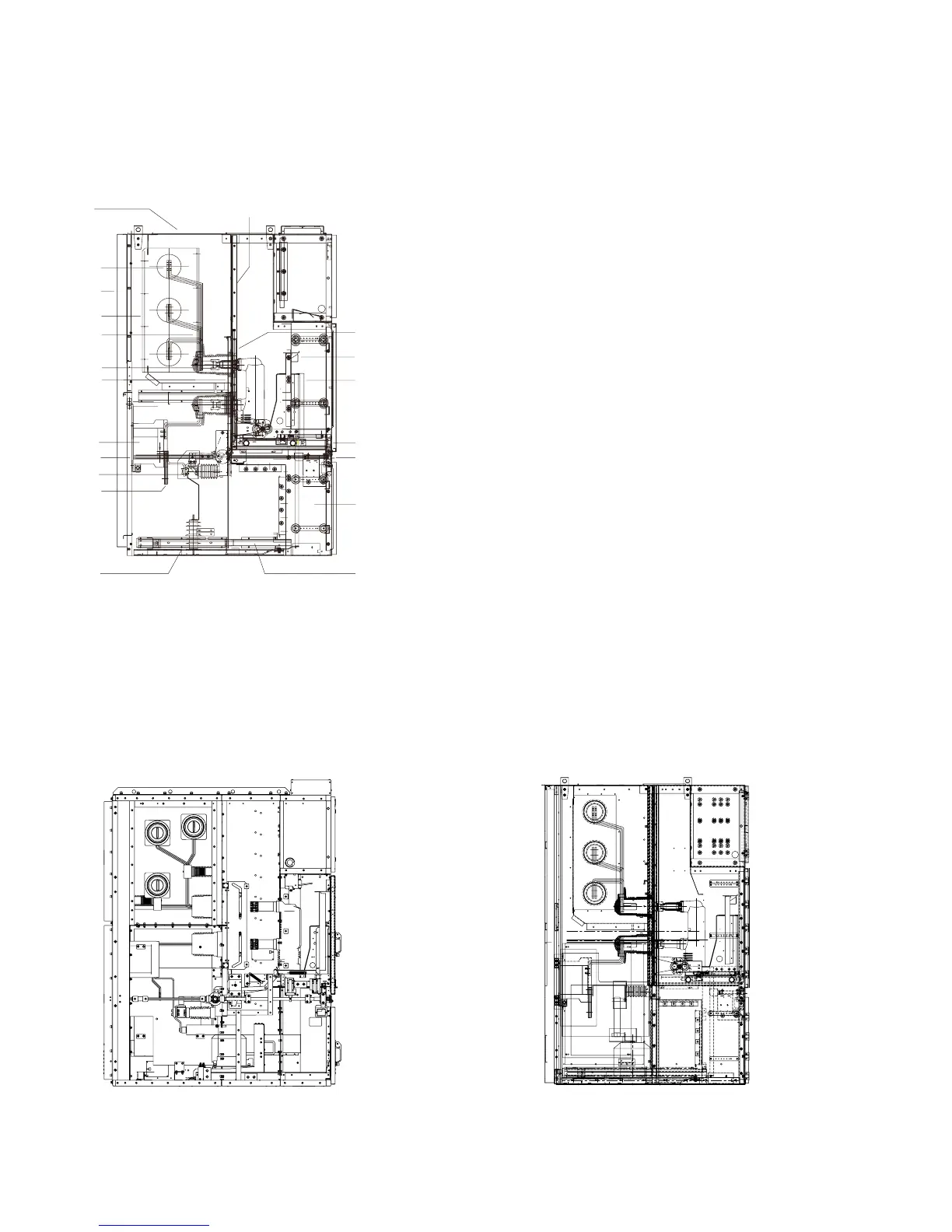
Switchgear structure
Figure 3/2: Typical feeder panel
A. Main bus compartment
B. Breaker compartment
C. Cable compartment
D. Low voltage compartment
1. Pressure relief plate
2. Enclosure
3. Cover of main busbar compartment (can be removed)
4. Branch busbar
5. Main busbar
6. Primary disconnect spouse
7. Primary disconnect
8. Current transformer
9. Earthing switch
10. Rear door interlock
11. Bottom plate
12. Pa
rtition between breaker compartment and busbar
compartment
13. Terminal block
14. Control plug
15. Shutter
16. Vacuum circuit breaker
17. Drive screw
18. Earthing switch operation mechanism
19. Control wire duct
20. Main earthing busbar
Figure 3/3: Incoming/feeder panel(1250/2500A) Figure 3/4: Incoming With fix VT panel (1250/2500A)
22
40
17