SecoGear 24kV-27kV Air Insulation Switchgear
29
Replacing the current transformer
Replace the current transformer if the assembled current
transformer cannot meet the function due to a change in the
load conditions. The steps are as follows:
Confirm the equipment be powered off and make sure
to follow proper safety measures.
Confirm the earthing switch is in OPEN position.
Ensure the marking on the mounting plate for the
installing position of the current transformer before
removing the four bolts to avoid the wrong position
with the hole of the copper connections after installing
the new current transformer;
Attention: The weight is heavy
because of the current
transformer installed in the mounting plate. It is
necessary to hold the mounting plate of the current
transformer to avoid the damage for the equipment
and personnel if the mounting plate drops down after
loosening the bolt.
• Remove the back cover of the enclosure
• Remove the connection bolt between the current transformer
and the vertical copper connections (See figure 6/1
0)
• Remove the secondary wires of the current transformer
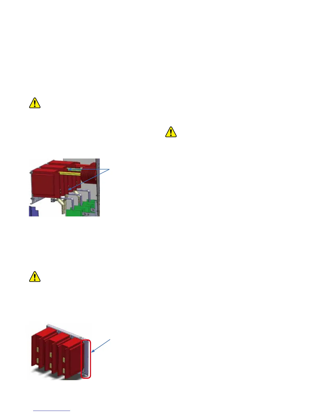
• Remove the 6 pcs of M8 bolts on the mounting plate of the
current transformer
Figure 6/11: Mounting plate of the current transformer
• Support the mounting plate of the current transformer and
then put on the ground
• Remove the four bolts which are used to fix the current
transformer, and remove the current transformer
• Replace the current tr
ansformer with new one and screw on
with the four bolts
• Assemble the current transformer in its place on mounting
plate and tighten the mounting plate by tightening the 10 pcs
of M8 bolts
• Screw on the bolts on the current transformer and the both
side copper connections
• Fix the bolt of the fixed contact of the earthing switch, but do
not fully tighten.
• Adjust the position of the fixed contact a
fter switching the
earthing switch in ON Position and then fasten
• OPEN the earthing switch
• Fasten the bolts on the copper connections and the current
transformer mounting with a torque wrench at a torque of 86
N-m
• Fix the insulation shield, and make sure it is in a vertical
position
• Connect the secondary connection of the CT and cover it
according to the requirements
• Assemble the back cover
and compartment separating plate
of switchgear
Copper
connections
Figure 6/10: Connection busbar between current transformer
and earthing switch
3 pcs of M8 bolts on each side