SecoGear 24kV-27kV Air Insulation Switchgear
27
Recommend torque (N-m)
Bolt size Without lubrication (oil) With lubrication (oil)
M8 26 10
M10 50 20
M12 86 40
M16 200 80
M20 300 120
• Tighten the bolt on the upper branch and main busbar. Ensure that applied torque is 86 N-m
• Tighten the bolt of the lower branch busbar and the current transformer. Ensure applied torque is 86 N-m
• Remove the inserted bolts on the driving mechanism of the shutter, and then put down
the shutters
Inspection and replacement of the
shutter mechanism
Replacing the earthing switch
In case of distortion or deformation, the driving mechanism of
the shutter shall be replaced.
The steps as follows:
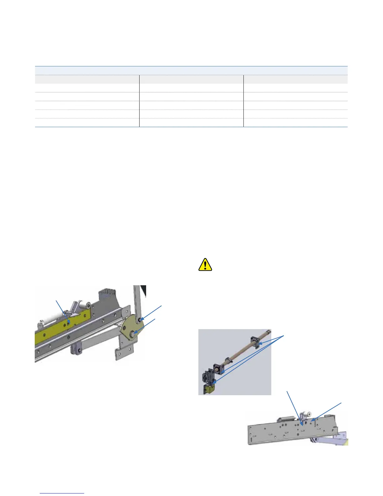
• Remove the split pins of the driving mechanism of the shutters
and connection bar (see figure 6/5)
• Screw off the bolt which is used to fix driving mechanism (see
figure 6/4)
The replacing of th
e earthing switch includes changing the
earthing switch along with labels for ON and OFF position, the
driving mechanism including driving gear assembly and drive
rod.
The steps for replacement are as follows.
Figure 6/4: Driving mechanism of the shutter
• Remove the 5 screws on the earthing bar, then remove the
earthing bar.
• Replace the 4 screws on the side plate of the shutter
mechanism, then remo
ve the side plate.
• Remove the 6 screws which used to fix the shutter
mechanism, replace with the new parts of shutter mechanism.
• Now replacement can be done with the above instructions
following the previous instructions in reverse order.
• Rack out the circuit breaker
• Remove the compartment separating plate
• Remove the cover plate on the right side in the cable
compartment
Ensure switchgear is in Power OFF position and turn
the earthing switch to the ON position.
Remove 6 fixing screws
which used to fix the
ES on the side sheet
Remove 4 fixing screws
Remove 6 fixing screws
• Loosen the fastening screws on the drive rod, but do not
remove completely.
Split pins
Bolt
Earthing bar