SecoGear 24kV-27kV Air Insulation Switchgear
26
Verify the switchgear is de-energized and the safety
measures are in place.
Don't fasten the bolt initially when locking the fixed
contact, Please fasten by applying torque when the
upper branch and main busbar, lower branch and the
current transformer are fixed;
Inspection and replacement of the
fixed contact and spout bushing
It is normal to find the fixed contact surface oxidized due to
current flow an
d environmental factors during period of service.
However if the surface becomes rusty due to wet or corrosive
conditions, the fixed contact must be replaced. The spout
bushing may be replaced depending of its condition.
Clean the contact with a cotton-free paper, and apply some
pure alcohol if necessary. Brush small amount of contact
lubrication grease (DE-G51 for example) on the surface after
wipi
ng. It is important to check any abnormal condition such as
the burning marks on the spout bushing, which may be caused
by the epoxy.
• Check and replace the fixed contact
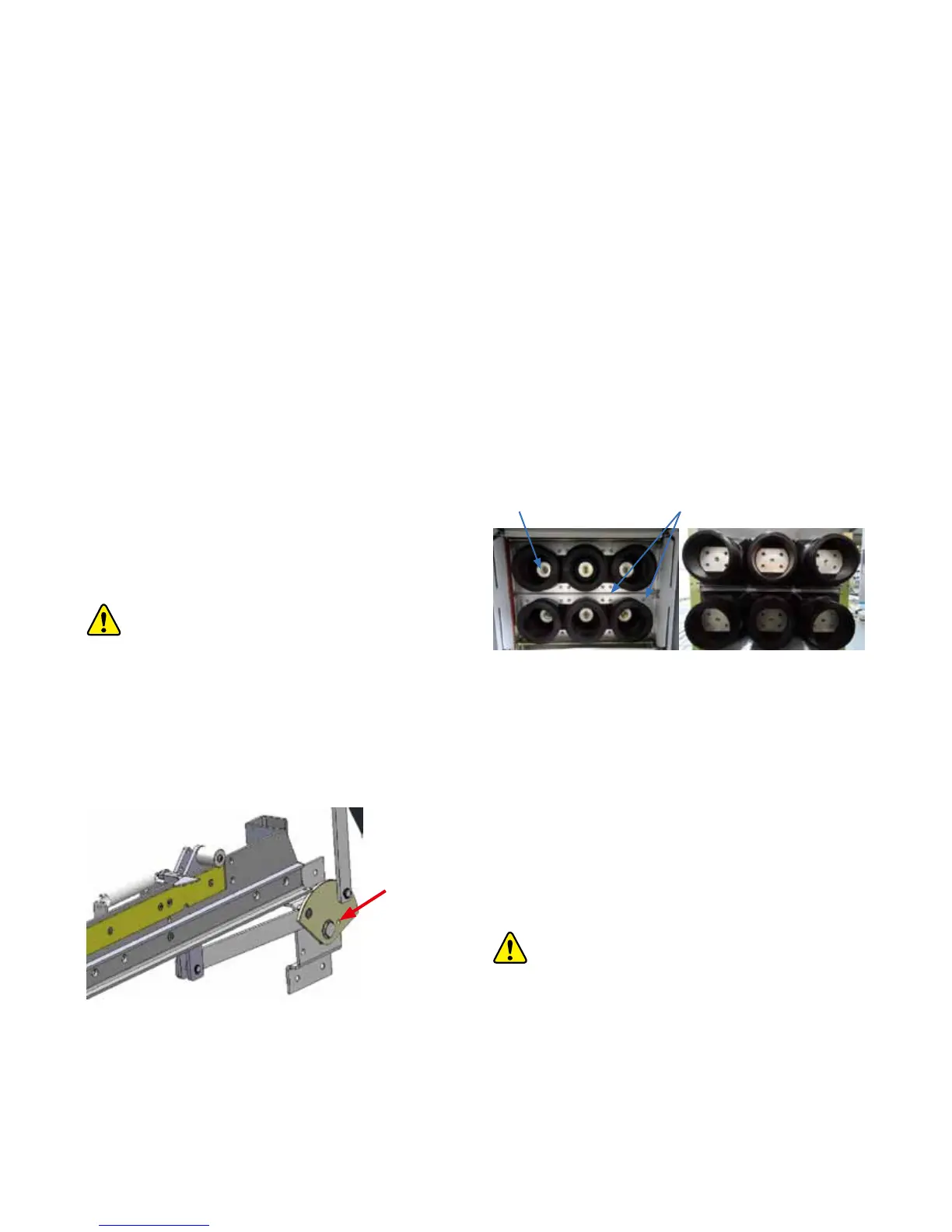
• Withdraw the circuit break . Open the shutter mechanism, and
insert two M8 bolts into the overlapping holes on the shafts
(See figure 6/2). Then the fixed contact along with the spout
bushing are visible.
Figure 6/2 : shutter mechanism
• Inspect the contacts. Replace the contact if the silver coating
on copper is worn, or the surface is corroded, damaged or
over heated.
• Remove the bolts on the fixed contact, and replace the fixed
contact (see figure 6/3)
• Replace the spout bushing
• Remove the bolt at the joint of the upper branch and main
busbar
• Remove the bolt at the joint of the lower branch busba
r and
the current transformer
• Remove the center bolt of the fixed contact and then remove
the vertical connections
Figure 6/3: Fixed contact and spout bushings
• Remove four fixing screws (M12) of the spout and then the
spout can be removed (see figure 6/3)
• Replace the new spout bushing and fasten the fixing screws
(M12). Inject glass glue in the clearance between the spout
bushing and the mounting m
etal frame
• Insert the upper and lower branch busbar into the spout
bushing, and fix the fixed contact
Attention:
The torque will be different based on different sizes of
the bolt and with/without lubrication. Corresponding torques of
different bolts identified below:
Silver plating fixed contact
Front Rear
Fixing screws