SecoGear 24kV-27kV Air Insulation Switchgear
25
Major Repairs and examples
Be sure to comply with the applicable safety
regulations when carrying out repairs.
Verify the switchgear is de-energized and the safety
measures are in place.
Pay attention to the direction of the tapered washers
and the bolted connection torque should reach 86 N-m.
• Open the main busbar compartment and check the tightening
torques for the busbar bolted connections
• Check the main busbar and branch
busbar for any dampness
or rust.
• Check all the sidewalls for any dampness or rust.
• Check the main busbar compartment for any unexpected
object.
• Restore the insulation shield and the pressure flap on the top
of the panel.
• Check the fitness of the fixed contact and the surface
condition.
• Open the cable compartment and check the cable connection
as wells as the connectors for color distortion.
• Ch
eck the sealing condition of through holes for the primary
and secondary cables.
• Check the heater condition.
• Check the breaker and cable compartment for unexpected
objects.
• Check the secondary connections of the CTs.
• Check the current terminals in the low voltage compartment
for the close loop of the secondary current circuit. Check
the protection relay, ammeter, energy meter, etc. on the CT
s
econdary are in service.
Inspection and replacement of the
main busbar
Unexpected objects in the busbar compartment, or a loose
bolted connection, may result heated joint or even phase fault.
The procedure to change the main busbar is as follow;
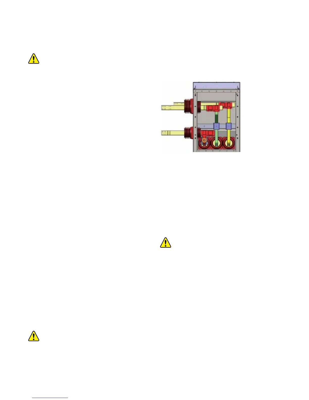
• Remove the rear covers on the busbar compartment, as well
as the same on the adjacent panels. Now the busbar is visible.
(see figure 6/1)
Figure 6/1: Busba
r after opening the rear cover
• Remove the pressure flap on the busbar compartment
• Remove the busbar insulation shield
• Remove the connection bolt on the main bar and branch
busbar
• Remove the busbar from the busbar compartment
• Install the new main busbar and fasten the joints
• Cover the busbar joints with insulation shield
• Reassemble the pressure flaps and rear cover panels for the
busbar compa
rtment