3.5 VENTILATION AND COOLING
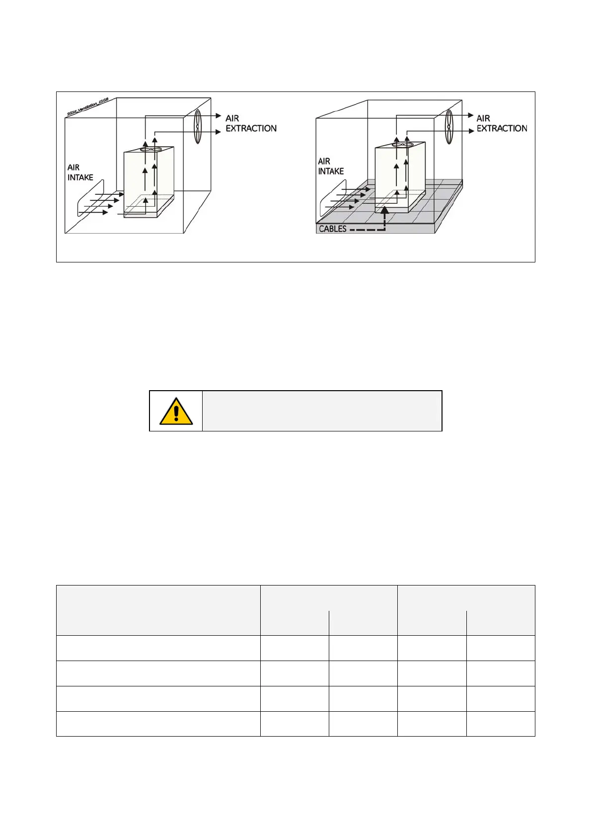
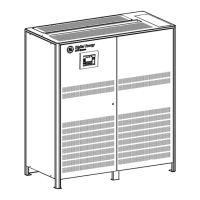
Fig. 3.5-1 Installation on plain floor Fig. 3.5-2 Installation on raised floor
The heat produced by the UPS is transferred to the environment by its ventilation.
Air inlets for UPS ventilation are located on the front of the UPS, while air outlets are on top of the
cabinet.
A suitable ventilation or cooling system must be installed to extract the heat from the UPS room.
NOTE !
Do not put anything on the top of the cabinet.
Air filtration systems could be required when the UPS operates in a dirty environment.
Contact your Dealer or the nearest Service Center for appropriate solutions.
In order to prevent overheating of the UPS, the available air intake flow rate must exceed the total air
exhaust flow rate requirement of the UPS system.
The below table indicates the heat dissipation at full load at PF = 0.9 lag. and charged battery, up to
3,280 ft (1,000 m) altitude, for cooling air 77°F (25°C) to 86°F (30°C).
Losses Cooling air flow
UPS rating with options
BTU / hr kW CFM m
3
/ h
SG Series 225 with 5
th
filter
82,902 15.5 2,661 4,521
SG Series 225 in eBoost™ Operation Mode
9,898 2.9 498 846
SG Series 300 with 5
th
filter
73,721 21.6 3,709 6,300
SG Series 300 in eBoost™ Operation Mode
12,287 3.6 618 1,050
Modifications reserved Page 15/40
OPM_SGS_ISG_M22_M30_2US_V010.doc Installation Guide S G S e r i e s 22 5 & 30 0 UL S2




 To Next Page