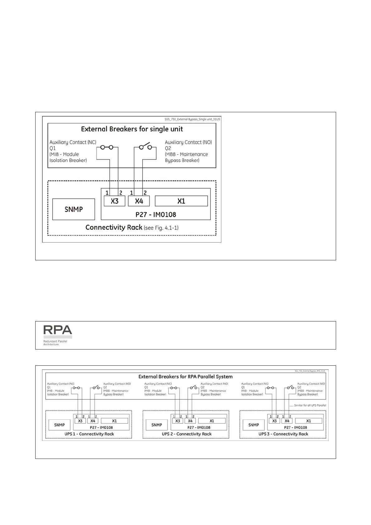
3.8.5 Interface to External Bypass for single unit
If the UPS system is equipped with an External Maintenance Bypass Switch, connect the NO (normally
open) voltage free auxiliary contact from the External Bypass Switch to X4 - 1, 2 of P27 – IM0108 -
Interface for External Bypass inserted in the Connectivity Rack.
When this NO (Normally Open) contact closes, the Inverter Output Contactor K7 opens and the Load
transfer to Inverter will be inhibited.
Fig. 3.8.5-1 Interface to External Bypass for single unit
SG Series 225 & 300 has to be
interfaced to the External Bypass
Auxiliary Contacts (NO) for safety
reasons.
This will prevent contactor K7
from closing when the external
bypass breaker is on.
The connections shown in the
diagram are mandatory.
3.8.6 Connections to External Bypass switch in case of RPA Parallel System
In a parallel system, this connection must be made between each UPS to a
separate AUX contact of the External Maintenance Bypass Switch.
Fig. 3.8.6-1 Connections to External Bypass switch in case of RPA Parallel System
Modifications reserved Page 29/40
OPM_SGS_ISG_M22_M30_2US_V010.doc Installation Guide SG S er i e s 2 25 & 30 0 UL S2
 Loading...