3.8.4 Battery and External Battery Breaker connection
_
+
Q1
0
O
F
F
I ON
Q2
0
O
F
F
I ON
BATTERY
PE
S
G
S
_
2
2
5
-
3
0
0
_
S
2
_
U
P
S
c
o
n
n
e
c
t
i
o
n
b
a
t
t
e
r
y
_
0
1
U
S
19
1718
6
7
20
9
8
21
10
22
11
15
14
3
4
16
5
1
2
3
4
1
2
3
4
Typical installation using
common NEMA two hole lugs
Fig. 3.8.4-1 Power connections Battery
Fix the cables on accessory “A” with the enclosed cable ties (see Fig. 3.8.2-1).
Battery Cable Terminations are to the Positive and Negative Terminals as shown above.
Connect wire to the Lugs using appropriate tools and appropriate torque.
Torque specification for Input/Output and DC power connections on Bus Bars: see Section 3.8.1.
Battery connection
+
Positive pole of the battery
-
Negative pole of the battery
Do not insert the Battery Fuses before the
commissioning!
PE
Battery ground
NOTE !
To meet standards concerning electromagnetic compliance, the connection
between the UPS and external Battery must be done by using a shielded cable or
suitable shielded (steel) conduit!
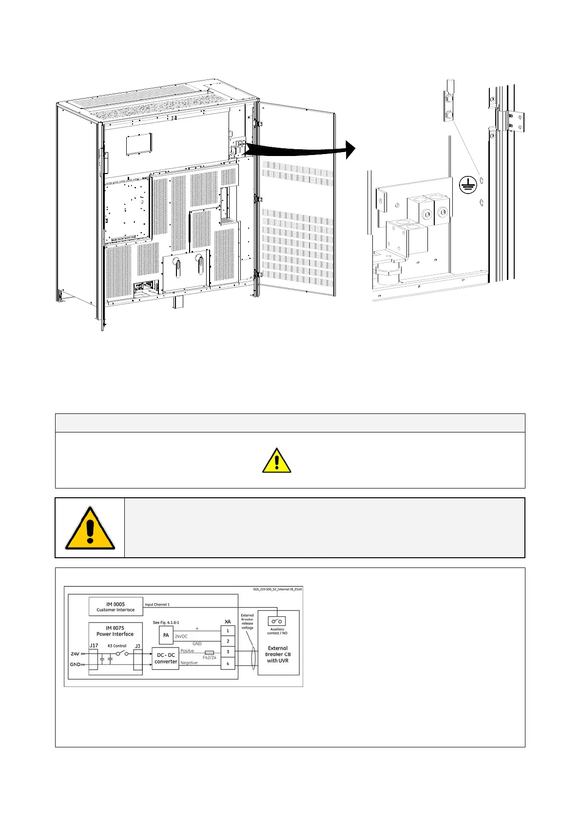
External Battery Breaker Release
Fig. 3.8.4-2 External battery breaker connection
For connection or disconnection of the
Battery an external breaker CB with UVR
is required.
The UVR of the external breaker must be
connected to terminal XA (see Fig. 4.1.6-1).
The release signal will allow, after the
Rectifier soft-start, the manual closure of
the breaker.
In either case, fuses or breaker, an auxiliary contact must signalize the closure of breaker or fuse
holder to Input channel 1 of the P4 - Customer Interface (see Section 4.1).
Contact must be open with Battery disconnected (Normally Open).
Modifications reserved Page 28/40
OPM_SGS_ISG_M22_M30_2US_V010.doc Installation Guide S G S e r i e s 22 5 & 30 0 UL S2