Table of contents Page
1 IMPORTANT SAFETY INSTRUCTIONS ........................................................................................................ 6
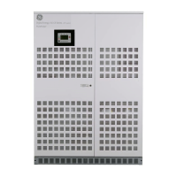
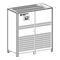
2 LAYOUT.......................................................................................................................................................... 9
2.1 LAYOUT SG Series 225 & 300 .......................................................................................................................................................9
3 INSTALLATION............................................................................................................................................ 10
3.1 TRANSPORT....................................................................................................................................................................................... 10
3.1.1 Dimensions and weight................................................................................................................................................................. 10
3.2 DELIVERY ............................................................................................................................................................................................ 11
3.3 STORAGE ............................................................................................................................................................................................ 11
3.3.1 Storage of the UPS .......................................................................................................................................................................... 11
3.3.2 Storage of battery........................................................................................................................................................................... 11
3.4 PLACE OF INSTALLATION ............................................................................................................................................................ 12
3.4.1 UPS location ....................................................................................................................................................................................... 12
3.4.2 Battery location................................................................................................................................................................................ 14
3.5 VENTILATION AND COOLING..................................................................................................................................................... 15
3.6 UNPACKING ...................................................................................................................................................................................... 16
3.7 ELECTRICAL WIRING...................................................................................................................................................................... 17
3.7.1 Utility input connection................................................................................................................................................................. 17
3.7.2 Input/output over current protection and wire sizing..................................................................................................... 18
3.7.3 Battery over current protection and wire sizing................................................................................................................ 19
3.8 WIRING CONNECTION.................................................................................................................................................................. 21
3.8.1 Power connections.......................................................................................................................................................................... 21
3.8.2 Power connection with common input utility..................................................................................................................... 23
3.8.3 Power connection dual input utility (option)........................................................................................................................ 25
3.8.4 Battery and External Battery Breaker connection ........................................................................................................... 28
3.8.5 Interface to External Bypass for single unit......................................................................................................................... 29
3.8.6 Connections to External Bypass switch in case of RPA Parallel System ................................................................ 29
3.8.7 Setup for SG Series 225 & 300 intended to be operated in eBoost™ Operation Mode.................................... 30
3.9 RPA PARALLEL SYSTEM CONNECTION .................................................................................................................................. 31
3.9.1 Power wiring of parallel units..................................................................................................................................................... 31
3.9.2 Parallel control bus connection................................................................................................................................................. 32
3.9.3 Control bus cable location........................................................................................................................................................... 34
4 CUSTOMER INTERFACE ............................................................................................................................. 36
4.1 CUSTOMER INTERFACE................................................................................................................................................................ 36
4.1.1 Serial Port J3 ...................................................................................................................................................................................... 37
4.1.2 Output free potential contacts .................................................................................................................................................. 37
4.1.3 Programmable input free contacts ......................................................................................................................................... 38
4.1.4 Gen Set Signaling (GEN ON)......................................................................................................................................................... 38
4.1.5 AUX external Maintenance Bypass ......................................................................................................................................... 38
4.1.6 Auxiliary Power Supply (APS) 24Vdc........................................................................................................................................ 38
4.1.7 EPO (Emergency Power Off) Input contact........................................................................................................................... 39
5 NOTES .......................................................................................................................................................... 40
5.1 NOTES FORM .................................................................................................................................................................................... 40
Modifications reserved Page 5/40
OPM_SGS_ISG_M22_M30_2US_V010.doc Installation Guide S G S e r i e s 22 5 & 30 0 UL S2