2 LAYOUT
2.1 LAYOUT SG Series 225 & 300
S
G
S
_
2
2
5
-
3
0
0
_
S
2
_
U
P
S
_
G
E
_
0
2
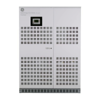
Fig. 2.1-1 SG Series 225 & 300 general view
S
G
S
_
2
2
5
-
3
0
0
_
S
2
_
U
P
S
_
0
3
0
O
F
F
Q2
I ON
Q1
I ON
0
O
F
F
4
3
2
1
2
Modifications reserved Page 9/40
OPM_SGS_ISG_M22_M30_2US_V010.doc Installation Guide S G S e r i e s 22 5 & 30 0 UL S2
3
4
1
43
2
1
15
14
13
12
98
20
19
5
6
7
17
16
18
21
10
22
11
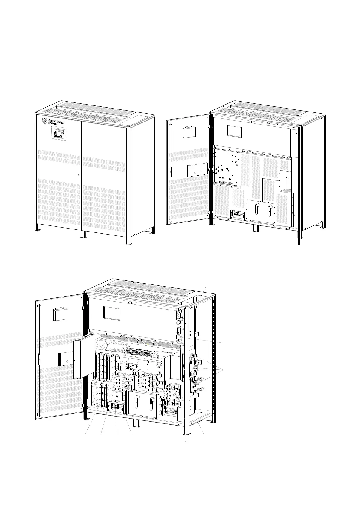
Fig. 2.1-2 SG Series 225 & 300 general view with open doors
S
G
S
_
2
2
5
-
3
0
0
_
S
2
_
U
P
S
_
0
4
0
O
F
F
Q1
I ON
I ON
Q2
0
O
F
F
1
4
3
2
CRXA XBPA
10
20
19
98
21
7
18
6
17
11
22
16
4
3
15
14
5
12
1
2
13
1
2
3
4
2
1
3
4
Fig. 2.1-3 SG Series 225 & 300 general view with optional 5
th
harmonic filter
and removed protection panels
1 Opening for top cable entry
(*)
2 Opening for bottom cable
entry
3 Compression lugs for Utility
input and Load output
4 Compression lugs for
external Battery
connection
CR Connectivity Rack
PA 24Vdc Auxiliary Power
Supply
XA Terminals for 24Vdc
Auxiliary Power Supply
connection
XB Terminals for EPO
connection
*) Remove this panel or
provide means to capture
metal filings from cutting
conduit entry holes.