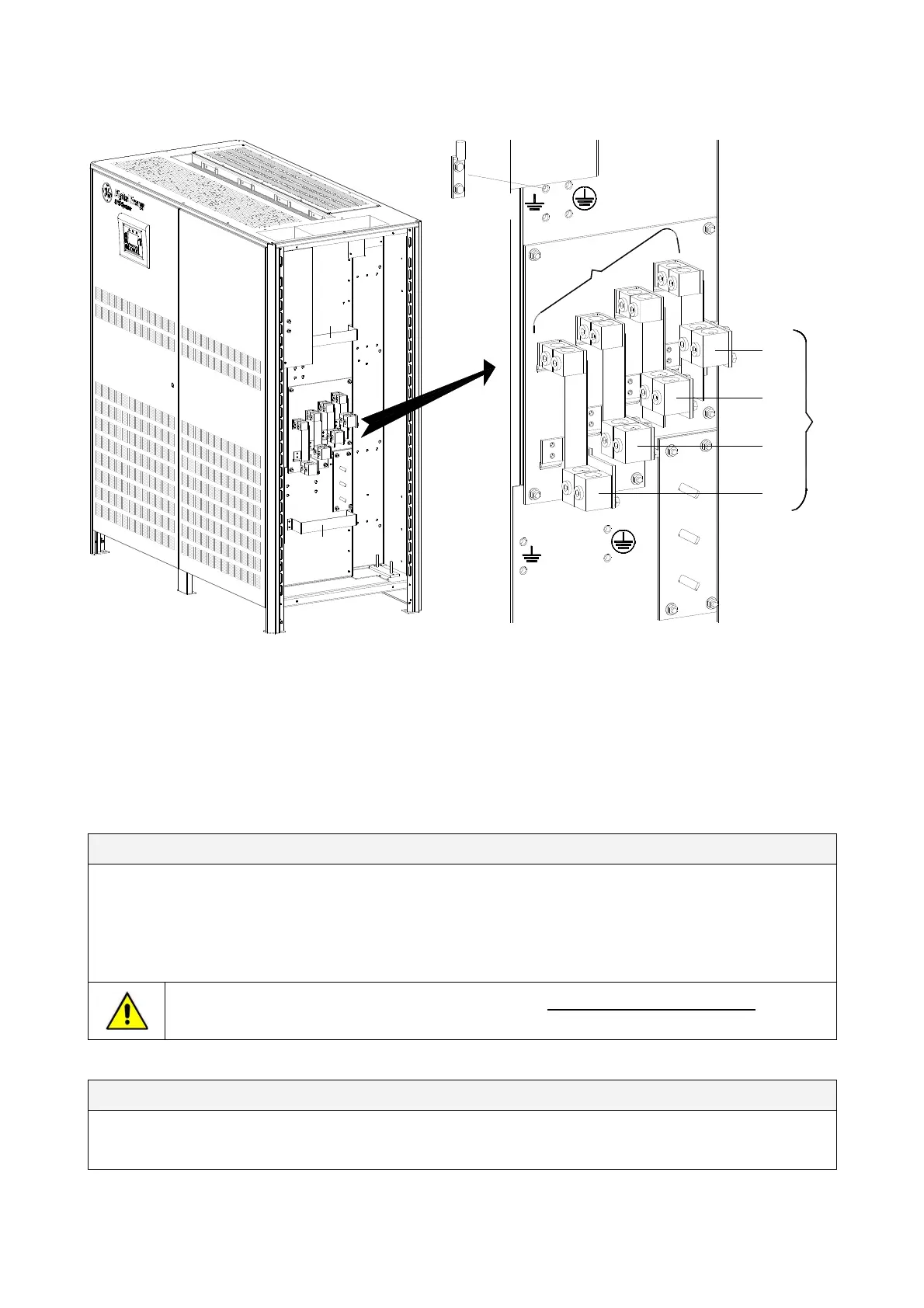
3.8.2 Power connection with common input utility
S
G
S
_
2
2
5-
3
0
0_
S
2_
U
PS
c
o
nn
e
c
t
i
on
c
o
m
m
o
n
_
G
E
_
01
U
S
A
A
PE
Input utility
PE Load
L
O
A
D
N
L3
L2
L1
N
L3-1
L2-1
L1-1
1 - INPUT RECTIFIER & BYPASS
PE Input utility
PE Load
common NEMA two hole lugs
Typical installation using
Fig. 3.8.2-1 Power connections Common Input Utility
Fix the cables on accessory “A” with the enclosed cable ties.
Cable terminations are to the Rectifier Input Lugs and Output Lugs as shown above.
Connect wire to the Lugs using appropriate tools and appropriate torque.
Torque specification for input/output and DC power connections on Bus Bars: see Section 3.8.1.
Common Input Rectifier / Bypass
L1-1
Rectifier + Bypass Phase A
L2-1
Rectifier + Bypass Phase B
L3-1
Rectifier + Bypass Phase C
N
Utility Neutral
PE Input Utility
Ground
The interconnection bus bars BR1, BR2 and BR3 MUST REMAIN CONNECTED
(see Fig.
3.8.3-3).
Output Load
L1
Load Phase A
L2
Load Phase B
L3
Load Phase C
N PE Load
Load Neutral Load Ground
Modifications reserved Page 23/40
OPM_SGS_ISG_M22_M30_2US_V010.doc Installation Guide S G S e r i e s 22 5 & 30 0 UL S2