CAUTION !
Panels “A, B, C, D, E and F” should never be removed or replaced with power applied
to the UPS.
This panel is in close proximity to 480V live bus bars.
Always disconnect the rectifier, bypass, load and battery sources from the UPS
before removing or replacing this panel.
If not serious injury or death could occur!
How to access the compression lugs for the cable connections.
Top entry cables
Please remove the plate
before drilling any holes
!
S
G
S
U
_
2
2
5
-
3
0
0
_
S
2
_
U
P
S
c
o
n
n
e
c
t
i
o
n
_
0
1
U
S
F
!
B
A
Please remove the plate
before drilling any holes
Bottom entry cables
Q1
0
O
F
F
I ON
Q2
0
O
F
F
I ON
E
D
C
12
1
1
4
3
2
13
2
5
3
4
67
8
11
19
20
10
14
15
16
22
1718
219
3
4
2
1
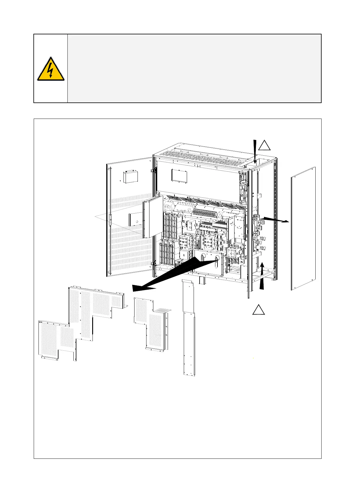
Fig. 3.8.1-1 Access to the input / output connections
To access input, output and Battery Connections proceed as follows:
• Unscrew bolts “B” to open the electronics “A”.
• Remove the protection panel “C”.
• Remove the protection panel “D”.
• Remove the protection panel “E”.
• Remove the UPS side panel “F”.
Modifications reserved Page 22/40
OPM_SGS_ISG_M22_M30_2US_V010.doc Installation Guide S G S e r i e s 22 5 & 30 0 UL S2