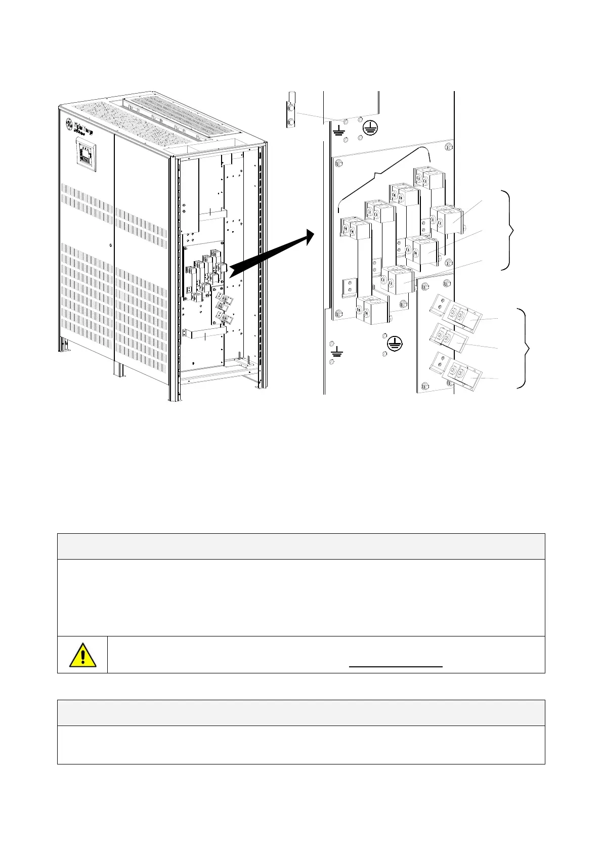
3.8.3 Power connection dual input utility (option)
A
PE Load
PE
Input utility
L1
L
OAD
L2
L3
N
PE Load
PE Input utility
1 - INPUT RECTIFIER
L2-1
L3-1
L1-1
N - Bypass
2 - INPUT BYPASS (option)
L3-2
L2-2
Typical installation using
common NEMA two hole lugs
L1-2
A
S
G
S
_
2
2
5
-
3
0
0_
S
2
_
U
P
S
c
on
n
e
c
t
i
o
n
s
e
par
a
t
e
_
G
E
_
0
1
U
S
Fig. 3.8.3-1 Power connections Dual Input Utility (option)
Fix the cables on accessory “A” with the enclosed cable ties.
Cable terminations are to the Rectifier/Bypass Input Lugs and Load Output Lugs as shown above.
Connect wire to the Lugs using appropriate tools and appropriate torque.
Torque specification for Input/Output and DC power connections on Bus Bars: see Section 3.8.1.
Dual Input Configuration Rectifier / Bypass (option)
L1-1
Rectifier Phase A
L1-2
Bypass Phase A
L2-1
Rectifier Phase B
L2-2
Bypass Phase B
L3-1
Rectifier Phase C
L3-2
Bypass Phase C
PE Input Utility
Ground
N - Bypass
Bypass Neutral
For dual input configurations, a neutral conductor is required from the bypass source
only. The interconnection links BR1, BR2 and BR3 MUST BE REMOVED
(see Fig. 3.8.3-3).
Output Load
L1
Load Phase A
L2
Load Phase B
L3
Load Phase C
N PE Load
Load Neutral Load Ground
Modifications reserved Page 25/40
OPM_SGS_ISG_M22_M30_2US_V010.doc Installation Guide S G S e r i e s 22 5 & 30 0 UL S2
 Loading...